75
Chapter 4 Calibration Procedures
Internal ADC Adjustment
4
4
Internal ADC Adjustment
The function generator stores calibration constants related to the gain
and offset of the internal ADC. Setup 6 must always be performed
before any other adjustments are attempted. The internal ADC is then
used as a source for the calibration constants generated in setup 7.
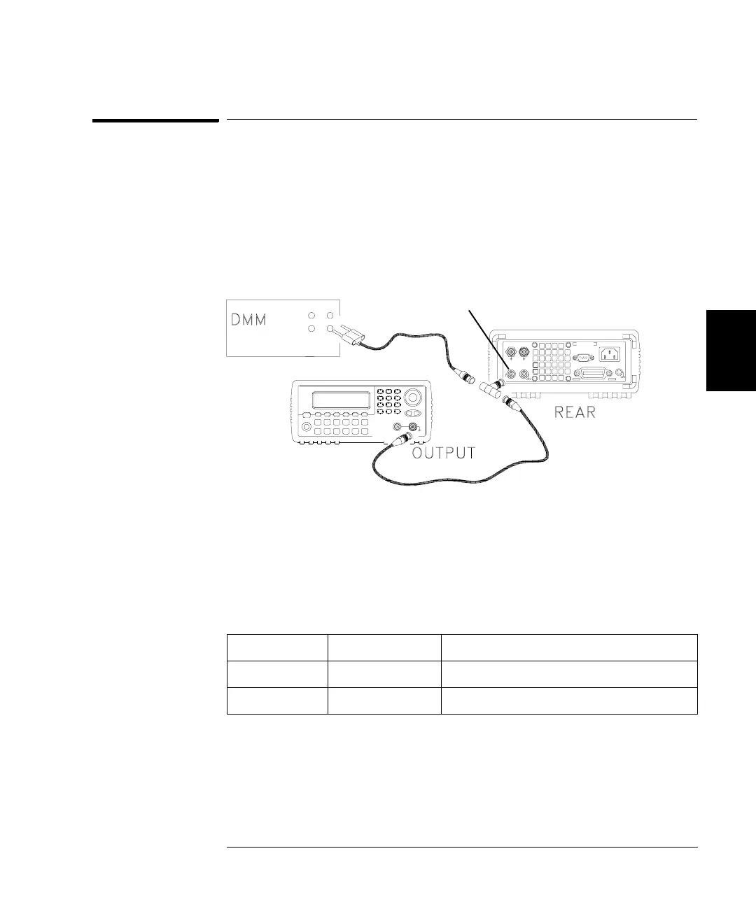
1 Make the connections as shown below.
2 Set the DMM to display 5
½ digits and measure the dc value.
Record the measurement.
3 Enter the following setup and use the numeric keypad or knob to enter
the measured value of the dc source.
* Constants are stored after completing this setup.
4 Disconnect all cables from the rear panel Modulation In connector.
Nominal Signal
Setup DC level
6* ~1 Vdc ±10% Calibrates the internal ADC.
Modulation In

 Loading...


