79
Chapter 4 Calibration Procedures
AC Amplitude (high-impedance) Adjustment
4
4
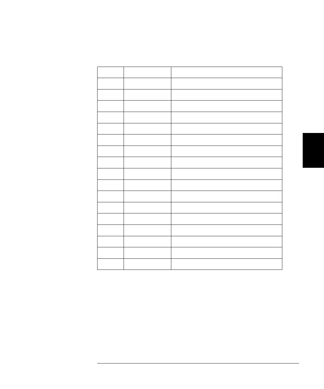
2 Use the DMM to measure the dc voltage at the front-panel Output
connector for each setup in the following table.
* Constants are stored after completing this setup.
3 Using the numeric keypad or knob, adjust the displayed voltage at each
setup to match the measured voltage. Select ENTER VALUE. (Entered
values are rounded to the nearest 100 µV.)
4 After performing setup 33:
a. If your calibration procedures require you to verify the adjustment
just made, exit the calibration menu and perform “AC Amplitude (high-
impedance) Verification”, on page 61.
b. If you are making all the adjustments and then verifying the instrument’s
performance, continue with the next procedure in this chapter.
Nominal Signal
Setup DC level
18 +0.015 V Output of -30 dB range
19* -0.015 V Output of -30 dB range
20 +0.05 V Output of -20 dB range
21* -0.05 V Output of -20 dB range
22 +0.15 V Output of -10 dB range
23* -0.15 V Output of -10 dB range
24 +0.50 V Output of 0 dB range
25* -0.50 V Output of 0 dB range
26 +0.15 V Output of -10 dB range (Amplifier In)
27* -0.15 V Output of -10 dB range (Amplifier In)
28 +0.50 V Output of 0 dB range (Amplifier In)
29* -0.50 V Output of 0 dB range (Amplifier In)
30 +1.5 V Output of +10 dB range (Amplifier In)
31* -1.5 V Output of +10 dB range (Amplifier In)
32 +5 V Output of +20 dB range (Amplifier In)
33* -5 V Output of +20 dB range (Amplifier In)

 Loading...


