Publication IASIMP-QS001C-EN-P - October 2009 73
Prepare the PanelView Plus Terminal Chapter 6
Install the ControlNet Interface Module
ControlNet only
Mount the PanelView Plus Terminal
2711P-K10C4D1 terminal and all controllers
For the purpose of this quick start, the PanelView Plus can be propped on a desktop.
For mounting instructions, see the PanelView Plus Terminals User Manual
, publication
2711P-UM001.
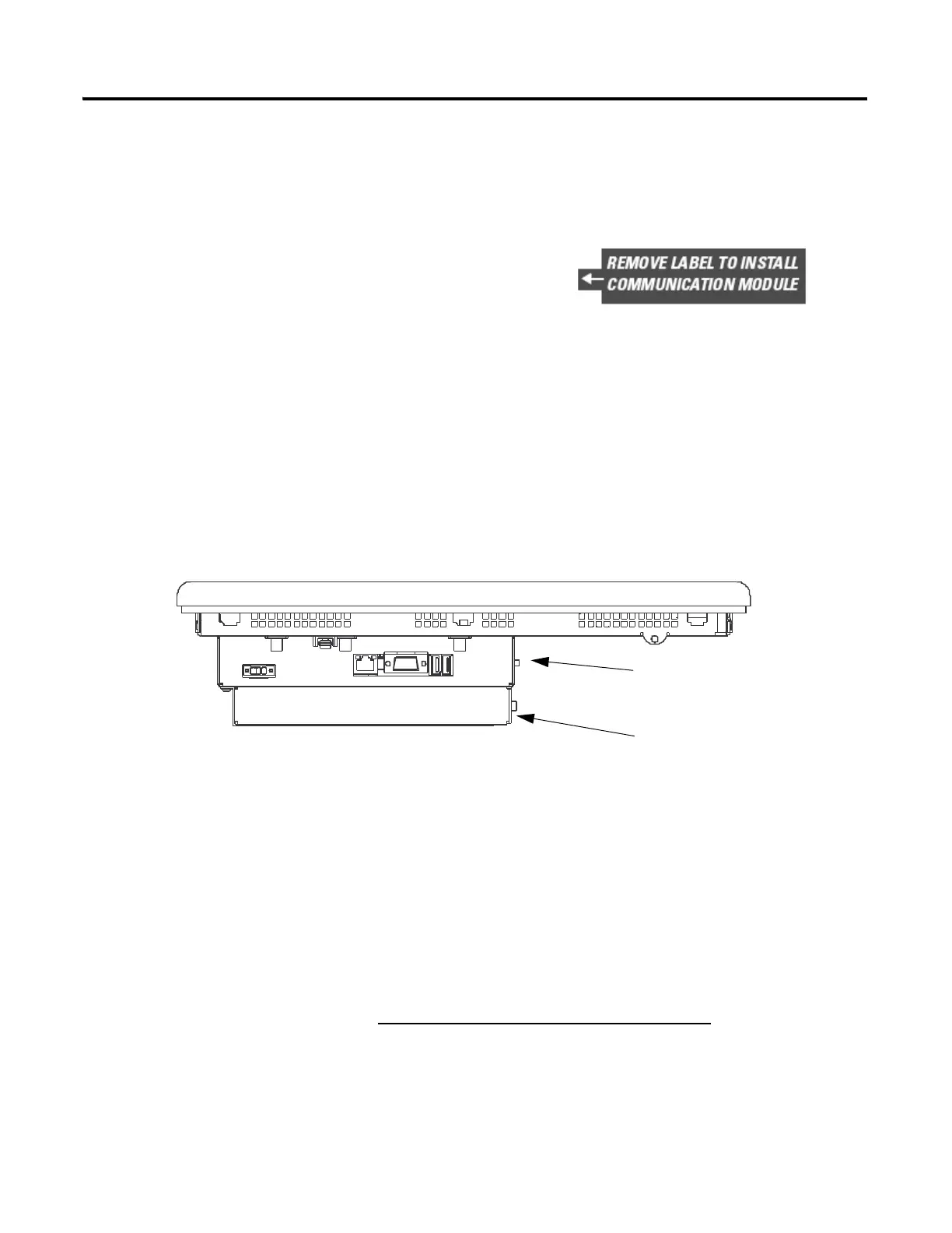
1. Remove the label covering the communication
module connector on the logic module.
2. Position the communication module over the logic module
so the connectors align.
3. Push down on the communication module until connectors
are firmly seated.
4. Tighten the 4 screws that secure the communication module
to the logic module.
Logic Module
Communication Module

 Loading...


