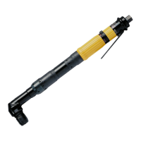
Consignes d'utilisation et de sécurité FR LTP51 H
22
© Atlas Copco Industrial Technique AB - 9836 938172 72
Après le cintrage, apposez la plaque prévue à cet effet, voir fig. C et mar-
quez le côté du toc de réaction qui doit être placé contre le support.
3 Montage
• Placez le toc de réaction dans la position souhaitée sur l’outil.
• Serrez l’écrou au couple de 70 Nm, 90 Nm ou 100 Nm, respectivement.
• Vérifiez régulièrement si l’écrou est bien serré.
4 Utilisation
• Appliquez le toc de réaction de la manière illustrée à la figure C – sens op-
posé à la rotation de l’outil – avant de mettre l’outil en marche.
• Ne posez jamais la main sur le toc de réaction ou à proximité de celui-ci
pendant l’utilisation de l’outil.
Table No. 1
LTP51 H006–19, LTP51 H008–13, LTP51 H012–13, LTP51 PH003–19,
LTP51 PH004–13 and LTP51 PH005–13
D = 54 mm, Wmin = 28.5 mm
Torque Nm 75 100 150 200 250
Angle α 21° 27° 37° 46° 55°
LTP51 H002–20, LTP51 H004–20, LTP51 PH001–20 and LTP51 PH002–20
D = 62 mm, Wmin = 39.5 mm
Torque Nm 250 300 400 500
Angle α 30° 35° 44° 50°
LTP51 H001–25, LTP51 PH0005–25 and LTP51 H0014-25
D = 63.5 mm, Wmin = 64.5 mm
Torque Nm 500 600 700 800 950
Angle α 32° 38° 43° 47° 53°
LTP51 H0007–25 and LTP51 PH0003–25
D = 83.5 mm, Wmin = 84.5 mm
Torque Nm 700 1000 1250 1500
Angle α 21° 30° 35° 41°
Example: LTP51 H002–20
D = 62 mm
500 Nm = 50°
 Loading...