Safety and operating instructions EN LTP51 H
6
© Atlas Copco Industrial Technique AB - 9836 938172 72
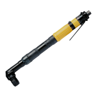
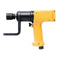
1 Shaping the reaction bar, Fig. A
The torque reaction bar must be shaped to fit a suitable fixed support. To avoid
overloading of the bearings for the tool drive and of the reaction bar, the
point of contact on the reaction bar should be within the shaded area (F),
see Fig. A.
• Measure the distance (L) for the hexagon sleeve to be used. Mark out points
(A and B) on a sheet of paper.
• Consult Table No.1 to find the angle (α) applicable to the diameter (D) of
the machine and the tightening torque in question. Draw a line from point
(A) in angle (α) from the centre line (A – C).
• Draw a line (B – E) at right angles (90
o
to the centre line (A – C) of the ma-
chine from point (B). Starting at point (B), draw two lines at angles of +15
o
and -15
o
respectively from the marked 90
o
-line.
• Mark the area (F) between the drawn lines.
• Adapt the shape of the reaction bar so that the point of contact (K) falls
within the marked area (F). The minimum breaking force is obtained if
the point of contact (K) is on or close to line (B – E).
• If the point of contact falls within angle (α) – in area (G) – there is a risk of
overloading of the bearings for the machine drive and deformation of the re-
action bar.
• If the point of contact is outside angles ± 15
o
– in areas (H) – there is a risk
of rapid wear of the hexagon sleeve and reduced torque accuracy.
2 Bending, Fig. B
• Heat the spot to red colour.
It is recommended to concentrate the heat to the inside radius in order not
to reduce the original width (W), see fig. B.
• After bending, allow to cool slightly in room temperature and then chill.
• In order for the torque reaction bar to be as light as possible it is recom-
mended that the section outside the bend be configured as shown in Fig. B.
After bending, attach the accompanying warning sign to the reaction bar,
see fig. C, and mark the side of the reaction bar that should be placed
against the support i a suitable way.
3 Assembly
• Place the reaction bar in the wanted position on the machine.
• Tighten the nut to a torque of 70 Nm, 90 Nm or 100 Nm respectively.
• Check regularly that the lock ring is firmly secured.
4 Use
• Apply the reaction bar according to figure C – opposite the direction of the
drive of the machine – before starting the machine.
• Never put your hand on or close to the reaction bar while the machine is
being used.
Table No. 1
LTP51 H006–19, LTP51 H008–13, LTP51 H012–13, LTP51 PH003–19,
LTP51 PH004–13 and LTP51 PH005–13
 Loading...