CB-100-22
Table of contents
1 Introduction............................................................................................................................................................3
2 Safety ....................................................................................................................................................................3
2.1 Authorized staff..............................................................................................................................................3
2.2 Residual risks ................................................................................................................................................3
2.3 Safety references...........................................................................................................................................3
2.3.1 General safety references.................................................................................................................. 3
3 Technical data .......................................................................................................................................................4
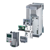
3.1 Modular design of the VARIPACK frequency inverter ...................................................................................6
4 Mounting................................................................................................................................................................7
4.1 Transport and storage ...................................................................................................................................7
4.2 Ventilation ......................................................................................................................................................7
4.3 Switch cabinet mounting................................................................................................................................8
4.4 Through-switch cabinet mounting (option).....................................................................................................9
4.4.1 Mounting work for through-switch cabinet mounting........................................................................ 11
4.5 Mounting in machinery room (option) ..........................................................................................................13
4.5.1 Mounting instructions for the IP21 kit............................................................................................... 14
4.6 Mounting the fixtures for power cables and control cables..........................................................................15
5 Electrical connection............................................................................................................................................16
5.1 Earth connection..........................................................................................................................................17
5.2 Power connections (voltage supply cable and motor cable)........................................................................17
5.3 Control connections (inputs and outputs) ....................................................................................................18
5.4 Operating modes .........................................................................................................................................20
5.4.1 Capacity control of the compressor depending on an external setpoint signal................................ 20
5.4.2 Capacity control of the compressor as a function of the evaporation pressure ............................... 21
5.5 Electromagnetic compatibility (EMC)...........................................................................................................22
5.5.1 Analysis of the harmonics FDU+6 .. FKU+260 ................................................................................ 23
5.6 Safe Torque Off (STO) ................................................................................................................................24
5.7 Schematic wiring diagrams..........................................................................................................................26
5.7.1 Schematic wiring diagrams semi-hermetic reciprocating compressors ........................................... 26
5.7.2 Schematic wiring diagrams semi-hermetic screw compressors ...................................................... 29
6 Control functions..................................................................................................................................................33
6.1 Extension module for pressure control ........................................................................................................35
7 Data communication with the VARIPACK frequency inverter .............................................................................37
7.1 Communication via the BEST SOFTWARE ................................................................................................37
7.2 Removable control panel (with display and keypad) ...................................................................................38
7.2.1 Kit for external mounting of the control panel .................................................................................. 38
7.2.2 Control panel setup and operation................................................................................................... 39
7.3 Interfaces for communication via ModbusRTU and ModbusTCP/IP .........................................................39
8 Commissioning of the VARIPACK frequency inverter.........................................................................................39
9 Fault messages and monitoring functions...........................................................................................................40
10 Maintenance........................................................................................................................................................41
 Loading...