ServSwitch™ DKM
158
I.4. Service Setup Extenders
For standard applications, you shouldn't need to make any adjustments to your ServSwitch™
DKM Media/KVM Extender. However, in certain circumstances, you may need to open the
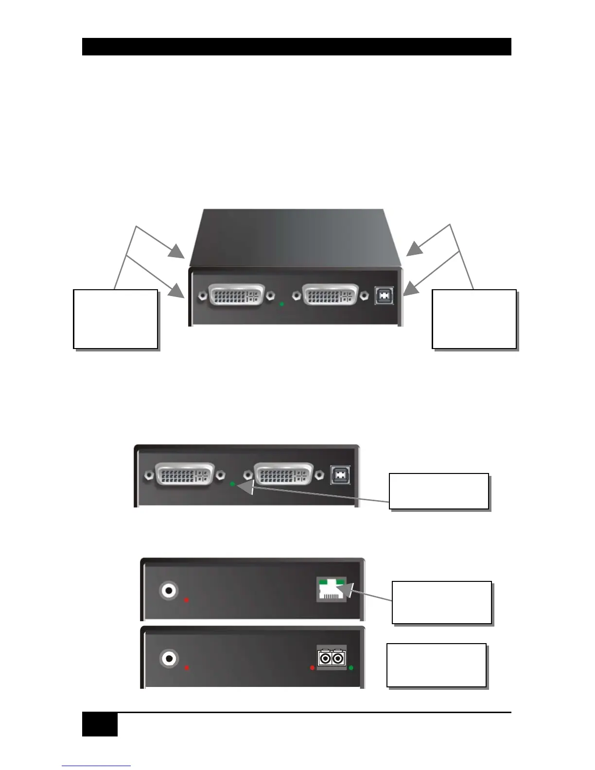
Local Unit and/or the Remote Unit. To open one of the units, unscrew the Philips-type screws
at both sides at the bottom of the device. Unscrew the UNC type screws on each side of the
monitor connectors. Carefully displace the lower and upper shells of the case.
The following diagnostic LEDs are used to indicate configuration changes:
The diagnostic LED ‘Video OK’ is located at the Local Unit between the both DVI-
connectors
The diagnostic LED ‘Video OK’ is located near to the CATx/Fibre- connectors
Diagnostic LED
Video OK
Fastening
screws on the
base
Fastening
screws on the
base
Diagnostic LED
Link Status
(CATx)
Diagnostic LED
Link Status
(Fibre)
 Loading...