RE 92050-01-X-B2/2019-08-23, BoschRexrothAG
43 Axial piston variable pump | A4VSO Series 10, 11 and 30
Installation instructions
Installation instructions
General
The axial piston unit must befilled with hydraulic fluid and
air bled during commissioning and operation. This must
also beobserved following alonger standstill astheaxial
piston unit may empty viathehydraulic lines.
Particularly inthe installation position "drive shaft
upwards", filling and air bleeding must becarried out
completely asthere is,for example, adanger ofdry
running.
The leakage in the housing area must be directed to the
reservoir via the highest drain port (T, K
1
, K
2
, R(T)).
For combination pumps, the leakage must bedrained off
ateach single pump.
Ifashared drain line isused for several units, make sure
that therespective case pressure ineach unit isnot
exceeded. The shared drain line must bedimensioned
toensure that themaximum permissible case pressure
ofall connected units isnot exceeded inany operating
conditions, particularly atcold start. Ifthis isnot possible,
separate drain line must belaid, ifnecessary.
To achieve favorable noise values, decouple all connecting
lines using elastic elements and avoid above-reservoir
installation.
In all operating conditions, the suction and drain lines must
flow into the reservoir below the minimum fluid level.
Thepermissible suction heighth
S
results from the total
pressure loss. However, it must not behigher than
h
Smax
=
800mm. The minimum suction pressure
atportSmust also not fall below 0.8bar abs. during
operation and during acold start.
Make sure toprovide adequate distance between suction
line and drain line forthe reservoir design. This prevents
the heated, and possible foaming return flow from being
drawn directly back into the suction line.
Notice
Incertain installation positions, an influence
ontheadjustment orcontrol can beexpected. Gravity,
dead weight and case pressure can cause minor
characteristic shifts and changes inactuating time.
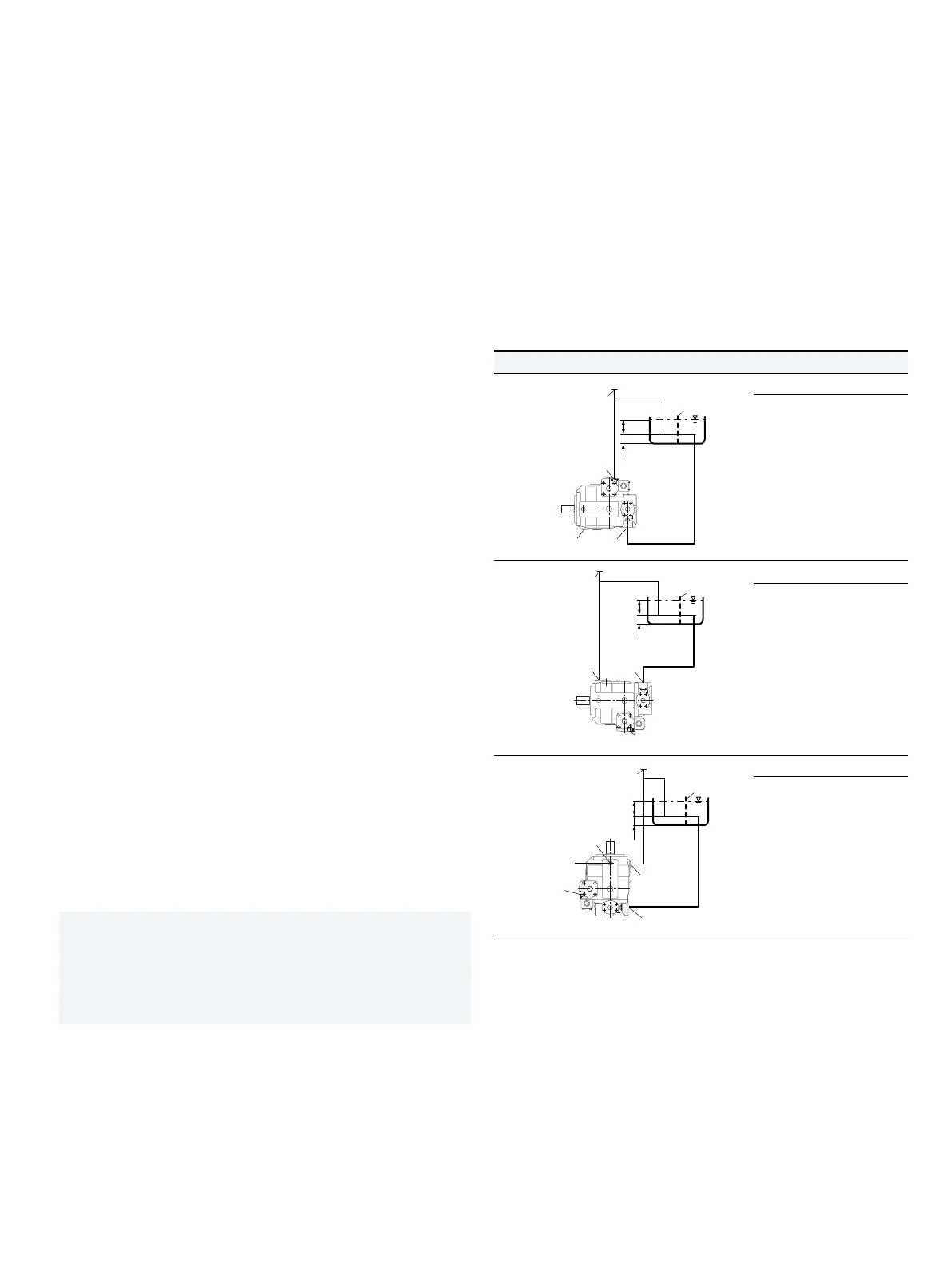
Installation position
See thefollowing examples 1 to7.
Further installation positions are available upon request.
Recommended installation position: 1 and 2
Below-reservoir installation (standard)
Below-reservoir installation means that theaxial piston unit
isinstalled outside ofthereservoir below theminimum
fluid level.
Installation position Air bleed Filling
1
SB
h
t min
h
min
R(L)
F
R(L) + F S + R(L)
2
SB
h
t min
h
min
R(L)
T
S
F
T + F S + T
3
SB
h
t min
h
min
R(L)
T
U
F
T + F S + T + U
For key, see page44.

 Loading...