149
Table 107 — VFD Terminal Designations
RETURN FAN — The return fan power exhaust assembly
consists of one belt-drive plenum fan. The return fan is a belt-
driven backward-curved fan. The plenum fan pressurizes the
plenum fan section so that the air can either be discharged hori-
zontally out the back of the unit or discharged through the re-
turn air section of the economizer.
ECONOMIZER MOTOR(S) — The economizer outside air
and return air dampers are motor actuator-driven through link-
ages. Communicating economizer motors controls their posi-
tion. The motor position is controlled by the MBB through the
communication bus. This allows for accurate control of the
motors as well as feedback information and diagnostics infor-
mation. The control has a self-calibration routine that allows
the motor position to be configured at initial unit start-up. The
motors are located on the economizer and can be reached
through the filter access door.
THERMISTORS AND PRESSURE TRANSDUCERS —
The unit is equipped with several thermistors for measurement
of temperatures. The thermistors are summarized in Table 108.
The units have two pressure transducers that are connected
to the low side of the system. These two pressure transducers
measure the low side pressure and are used for low pressure
protection and coil freeze protection.
The units also have two pressure transducers that are con-
nected to the high side of the system. These two pressure trans-
ducers measure the discharge pressure and are used to cycle the
condenser fans to maintain head pressure.
By using the high and low side pressure transducers, the
ComfortLink controls display the high and low side pressures
and saturation temperatures and a normal gage set is not
required.
SMOKE DETECTOR — The units can be equipped with an
accessory smoke detector located in the supply or return air.
The detector is wired to the ComfortLink controls and, if acti-
vated, will stop the unit by means of a special fire mode. The
smoke detector can also be wired to an external alarm system
through TB201 terminals 1 and 2. The sensor is located in the
supply or return air sections.
FILTER STATUS SWITCH — The units can be equipped
with optional accessory filter status switch on both the return
and supply (post) air filters. The switch measures the pressure
drop across the filters and closes when an adjustable pressure
set point is exceeded. The sensors are located in the control
panel. The return filter switch is connected to terminals 1 and 2
on TB203. The 180-ohm resistor is on the terminals for when
the filter pressure is used. The resistor must be removed for the
switch to operate properly. The supply filter switch is connect-
ed to terminals 3 and 4 on TB203. The 180-ohm resistor must
be removed.
FILTER PRESSURE SENSOR — The units can be equipped
with optional accessory filter pressure sensors on both the re-
turn and supply (post) air filters. The sensor measures the pres-
sure drop across the filters and outputs a 4 to 20 mA signal that
is read by the ComfortLink controls. The sensors are located in
the control panel. The return filter sensor is connected to termi-
nals 1 and 2 on TB203. The supply filter sensor is connected
to terminals 3 and 4 on TB203. The 180-ohm resistor is on the
terminals for when the filter pressure sensors are used. The re-
sistors must remain for the sensors to operate properly.
NOTE: ComfortLink controls can accept either the filter status
switch OR the filter pressure sensor. It cannot accept both at
the same time.
FAN STATUS SWITCH — The units can be equipped with
an optional fan status switch that will monitor the pressure rise
across the indoor fans.
RETURN AIR CO
2
SENSOR — The unit can be equipped
with a return air IAQ CO
2
sensor that is used for the demand
controlled ventilation. The sensor is located in the return air
section and can be accessed from the filter access door.
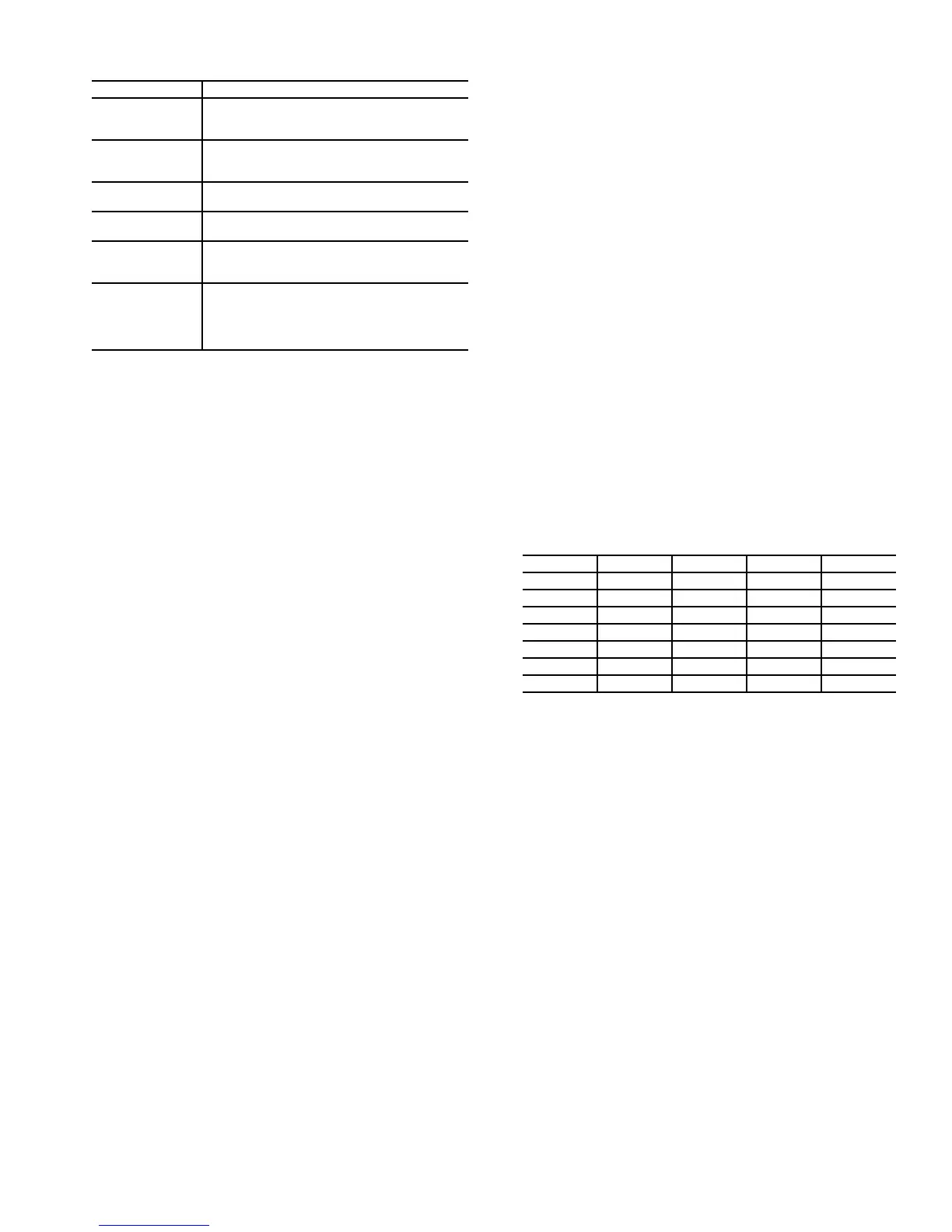
BOARD ADDRESSES — Each board in the system has an
address. The MBB has a default address of 1 but it does have
an instance jumper that should be set to 1 as shown in Fig. 34.
For the other boards in the system there is a 4-dip switch head-
er on each board that should be set as shown below.
0 = On; 1 = Off
Accessory Control Components — In addition to
the factory-installed options, the units can also be equipped
with several field-installed accessories that expand the control
features of the unit. The following hardware components can
be used as accessories.
ROOM THERMOSTATS — The ComfortLink controls sup-
port a conventional electro-mechanical or electronic thermostat
that uses the Y1, Y2, W1, W2, and G signals. The control also
supports an additional input for an occupied/unoccupied com-
mand that is available on some thermostats. The ComfortLink
controls can be configured to run with up to 6 stages of capaci-
ty. The room thermostat is connected to TB201.
The ComfortLink controls also support the use of space
temperature sensors and can be used with the T55 and T56 sen-
sors. The controls can also be used with CCN communicating
T58 room sensor. The T55 and T56 sensors are connected to
TB201 terminals 1, 2, and 3. The T58 sensor is connected to
the CCN connections on COMM board. Whenever a unit
equipped with heat is operated without a thermostat, the user
must install the red jumpers from R to W1, and W2 on TB201
for the heat function to work correctly.
TERMINAL FUNCTION
U1 Three-phase main circuit input power supply
V1
W1
U2 Three-Phase AC Output to Motor, 0 V to
Maximum Input Voltage LevelV2
W2
X1-11 (GND) Factory-supplied jumper
X1-12 (D-COM)
X1-10 (+24 V) Factory-supplied jumper
X1-13 (DI-1)
X1-10 (+24 V) Start Enable 1 (Factory-supplied jumper).
When opened the drive goes to emergency
stop.
X1-16 (DI-4)
X1-28 (SCR) Factory wired for local equipment network LEN
communicationX1-29 (B+)
X1-30 (B-)
X1-31 (AGND)
X1-32 (SCR)
BOARD SW1 SW2 SW3 SW4
RXB0000
EXB1000
SCB0000
CEM0000
EXV-A1000
EXV-B0100
EXV-C0000
 Loading...


