62
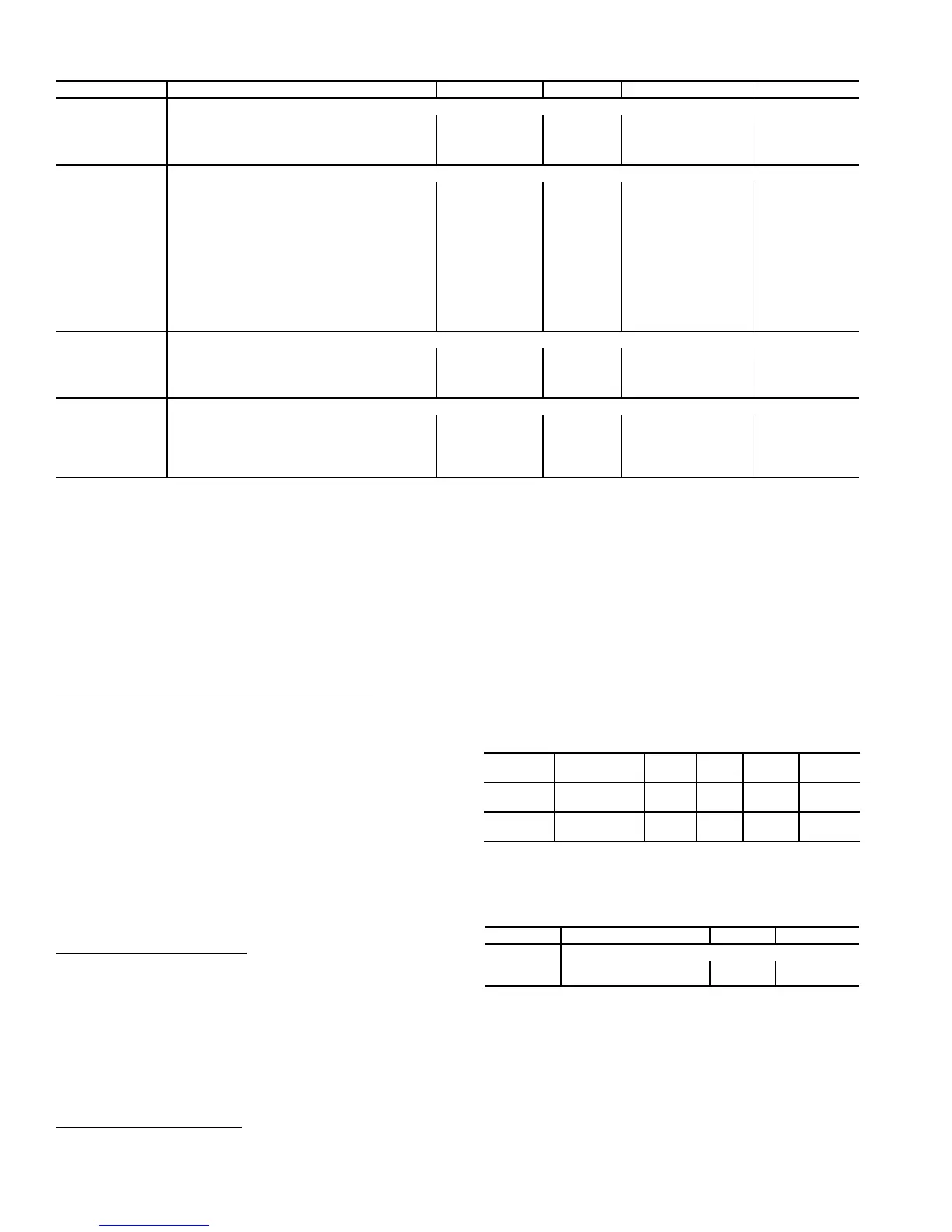
Table 34 — Heating Configuration
*Some defaults are model number dependent.
NOTE: If the user does not relocate this sensor for the 2-stage
electric or gas heating types and is under CCN Linkage, then
the control will send a heating mode (if present)
unconditionally to the linkage coordinator in the CCN zoning
system regardless of the leaving-air temperature.
HEAT MODE SELECTION PROCESS — There are two
possible heat modes that the control will call out for heating
control: HVAC Mode = LOW HEAT and HVAC Mode =
HIGH HEAT. These modes will be called out based on control
type (C.TYP).
VAV- R AT (
C.TYP = 1) and VAV-SPT (C.TYP = 2) — There
is no difference in the selection of a heating mode for either
VAV-RAT or VAV-SPT, except that for VAV-SPT, space tem-
perature is used in the unoccupied period to turn on the supply
fan for 10 minutes before checking return-air temperature. The
actual selection of a heat mode, LOW or HIGH for both con-
trol types, will be based upon the controlling return-air
temperature.
With sufficient heating demand, there are still conditions
that will prevent the unit from selecting a heat mode. First, the
unit must be configured for a heat type (Configuration
HEAT
HT.CF not equal to “NONE”). Second, the unit has a
configuration which can enable or disable heating in the
occupied period except for a standard morning warmup cycle
(Configuration
HEAT
OC.EN). See descriptions above in
the Setting Up the System section for more information.
Tstat-Multi-Stage (
C.TYP = 3) — With thermostat control
the W1 and W2 inputs determine whether the HVAC Mode is
LOW or HIGH HEAT.
W1 = ON, W2 = OFF: HVAC MODE = LOW HEAT*
W2 = ON, W2 = ON: HVAC MODE = HIGH HEAT
*If the heating type is either 2-stage electric or 2-stage gas, the
unit may promote a low heat mode to a high heat mode.
NOTE: If W2 = ON and W1 is OFF, a “HIGH HEAT” HVAC
Mode will be called out but an alert (T422) will be generated.
See Alarms and Alerts section on page 115.
SPT Multi-Stage (
C.TYP = 4) — The unit is free to select a
heating mode based on space temperature (SPT).
If the unit is allowed to select a heat mode, then the next
step is an evaluation of demand versus set point. At this point,
the logic is the same as for control types VAV-RAT and
VAV-SPT, (C.TYP = 1,2) except for the actual temperature
compared against set point. See Temperature Driven Heat
Mode Evaluation section below.
TEMPERATURE DRIVEN HEAT MODE EVALUATION —
This section discusses the technique for selecting a heating
mode based on temperature. Regardless of whether the unit is
configured for return air or space temperature the logic is ex-
actly the same. For the rest of this discussion, the temperature
in question will be referred to as the controlling temperature.
First, the occupied and unoccupied heating set points under
Setpoints must be configured.
Then, the heat/cool set point offsets under Configura-
tion
BP
D.LV.T should be set. See Table 35.
Related operating modes are under Operating Modes
MODE.
The first thing the control determines is whether the unit
is in the occupied mode (OCC) or in the temperature compen-
sated start mode (T.C.ST ). If the unit is occupied or in tempera-
ture compensated start mode, the occupied heating set point
(OHSP) is used. In all other cases, the unoccupied heating
setpoint (UHSP) is used.
The control will call out a low or high heat mode by
comparing the controlling temperature to the heating set point
and the heating set point offset. The set point offsets are used as
additional help in customizing and tweaking comfort into the
building space. See Fig. 14 for an example of offsets.
ITEM EXPANSION RANGE UNITS CCN POINT DEFAULT
HEAT HEATING CONFIGURATION
HT.CF Heating Control Type 0 - 5 HEATTYPE 0*
HT.SP Heating Supply Air Setpt 80 - 120 dF SASPHEAT 85
OC.EN Occupied Heating Enabled Yes/No HTOCCENA No
LAT.M MBB Sensor Heat Relocate Yes/No HTLATMON No
SG.CF STAGED HEAT CONFIGS
HT.ST Staged Heat Type 0 - 3 HTSTGTYP 0*
CAP.M Max Cap Change per Cycle 5 - 45 HTCAPMAX 45*
M.R.DB St.Ht DB min.dF/PID Rate 0 - 5 HT_MR_DB 0.5
S.G.DB St.Heat Temp. Dead Band 0 - 5 ^F HT_SG_DB 2
RISE Heat Rise dF/sec Clamp 0.05 - 0.2 HTSGRISE 0.06
LAT.L LAT Limit Config 0 - 20 ^F HTLATLIM 10
LIM.M Limit Switch Monitoring? Yes/No HTLIMMON Yes
SW.H.T Limit Switch High Temp 80 - 210 dF HT_LIMHI 170*
SW.L.T Limit Switch Low Temp 80 - 210 dF HT_LIMLO 160*
HT.P Heat Control Prop. Gain 0 - 1.5 HT_PGAIN 1
HT.D Heat Control Derv. Gain 0 - 1.5 HT_DGAIN 1
HT.TM Heat PID Rate Config 30 - 300 sec HTSGPIDR 90*
HH.CF HYDRONIC HEAT CONFIGS
HW.P Hydronic Ctl.Prop. Gain 0 - 1.5 HW_PGAIN 1
HW.I Hydronic Ctl.Integ. Gain 0 - 1.5 HW_IGAIN 1
HW.D Hydronic Ctl.Derv. Gain 0 - 1.5 HW_DGAIN 1
HW.TM Hydronic PID Rate Config 15 - 300 sec HOTWPIDR 90
ACT.C HYDR.HEAT ACTUATOR CFGS.
SN.1 Hydronic Ht.Serial Num.1 0 - 9999 HTCL_SN1 0
SN.2 Hydronic Ht.Serial Num.2 0 - 6 HTCL_SN2 0
SN.3 Hydronic Ht.Serial Num.3 0 - 9999 HTCL_SN3 0
SN.4 Hydronic Ht.Serial Num.4 0 - 254 HTCL_SN4 0
C.A.LM Hydr.Ht.Ctl.Ang.Lo Limit 0-90 HTCLCALM 85
ITEM EXPANSION RANGE UNITS
CCN
POINT
DEFAULT
OHSP
Occupied Heat
Setpoint
55-80 dF OHSP 68
UHSP
Unoccupied
Heat Setpoint
40-80 dF UHSP 55
ITEM EXPANSION RANGE CCN POINT
MODE MODES CONTROLLING UNIT
OCC Currently Occupied ON/OFF MODEOCCP
T.C.ST Temp.Compensated Start ON/OFF MODETCST
 Loading...


