3
GENERAL
This book contains Start-Up, Controls, Operation, Trouble-
shooting and Service information for the 48/50N Series rooftop
units. See Table 1. These units are equipped with ComfortLink
controls version 2.0 or higher. Use this guide in conjunction
with the separate installation instructions packaged with the
unit.
The 48/50N Series units provide ventilation, cooling, and
heating (when equipped) in variable air volume (VAV), staged
air volume (SAV™) and constant volume (CV) applications.
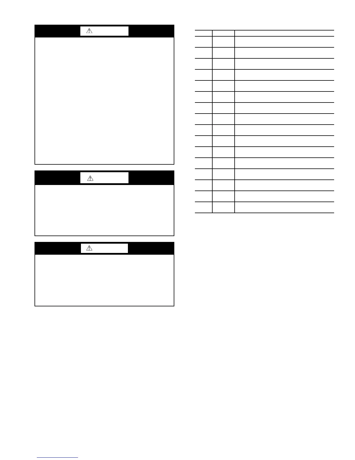
Table 1 — N Series Product Line
LEGEND
The 48/50N units contain the factory-installed ComfortLink
control system which provides full system management. The
main base board (MBB) stores hundreds of unit configuration
settings and 8 time of day schedules. The MBB also performs
self diagnostic tests at unit start-up, monitors the operation of
the unit, and provides alarms and alert information. The system
also contains other optional boards that are connected to the
MBB through the Local Equipment Network (LEN). Informa-
tion on system operation and status are sent to the MBB pro-
cessor by various sensors and optional board(s) that are located
at the unit and in the conditioned space. Access to the unit con-
trols for configuration, set point selection, schedule creation,
and service can be done via local display, using the supplied
Navigator™ device, or through the Carrier Comfort Network
®
(CCN) using ComfortVIEW™ software, Network Service
Tool, or other CCN device.
The ComfortLink system controls all aspects of the rooftop.
It controls the supply-fan motor, compressors, and economizer
to maintain the proper temperature conditions. The controls
also cycle condenser fans to maintain suitable head pressure.
All units are equipped with a supply fan VFD (variable fre-
quency drive). The VAV units utilize the VFD for supply duct
pressure control. The ComfortLink controls can directly control
the speed of the VFD based on a static pressure sensor input. In
addition, the ComfortLink controls can adjust the building pres-
sure using an optional VFD controlled power exhaust or return
fan controlled from a building pressure sensor. The control
safeties are continuously monitored to prevent the unit from op-
erating under abnormal conditions. Sensors include pressure
transducers and thermistors. For units on CV applications, the
ComfortLink controls will direct the VFD to drive the supply
fan at low speed for low cool or heat demand and high speed on
high cool or heat demand.
WARNING
DO NOT USE TORCH to remove any component. System
contains oil and refrigerant under pressure.
To remove a component, wear protective gloves and gog-
gles and proceed as follows:
a. Shut off electrical power to unit.
b. Recover refrigerant to relieve all pressure from sys-
tem using both high-pressure and low pressure ports.
c. Traces of vapor should be displaced with nitrogen
and the work area should be well ventilated. Refrig-
erant in contact with an open flame produces toxic
gases.
d. Cut component connection tubing with tubing cutter
and remove component from unit. Use a pan to catch
any oil that may come out of the lines and as a gage
for how much oil to add to the system.
e. Carefully unsweat remaining tubing stubs when nec-
essary. Oil can ignite when exposed to torch flame.
Failure to follow these procedures may result in personal
injury or death.
CAUTION
DO NOT re-use compressor oil or any oil that has been
exposed to the atmosphere. Dispose of oil per local codes
and regulations. DO NOT leave refrigerant system open to
air any longer than the actual time required to service the
equipment. Seal circuits being serviced and charge with
dry nitrogen to prevent oil contamination when timely
repairs cannot be completed. Failure to follow these proce-
dures may result in damage to equipment.
WARNING
What to do if you smell gas:
1. DO NOT try to light any appliance.
2. DO NOT touch any electrical switch, or use any
phone in your building.
3. IMMEDIATELY call your gas supplier from a neigh-
bor’s phone. Follow the gas supplier’s instructions.
4. If you cannot reach your gas supplier call the fire
department.
UNIT SIZE APPLICATION
48N2 All
Vertical Suppy/Return, CV/SAV ComfortLink
Controls
48N3 All
Vertical Supply/Return, VAV ComfortLink
Controls
48N4 All
Horizontal Suppy/Return, CV/SAV ComfortLink
Controls
48N5 All
Horizontal Suppy/Return, VAV ComfortLink
Controls
48N6 All
Vertical Suppy/Horizontal Return, CV/SAV
ComfortLink Controls
48N7 All
Vertical Supply/Horizontal Return, VAV
ComfortLink Controls
48N8 All
Horizontal Suppy/Vertical Return, CV/SAV
ComfortLink Controls
48N9 All
Horizontal Suppy/Vertical Return, VAV
ComfortLink Controls
50N2 All
Vertical Suppy/Return, CV/SAV ComfortLink
Controls
50N3 All
Vertical Supply/Return, VAV ComfortLink
Controls
50N4 All
Horizontal Suppy/Return, CV/SAV ComfortLink
Controls
50N5 All
Horizontal Suppy/Return, VAV ComfortLink
Controls
50N6 All
Vertical Suppy/Horizontal Return, CV/SAV
ComfortLink Controls
50N7 All
Vertical Supply/Horizontal Return, VAV
ComfortLink Controls
50N8 All
Horizontal Suppy/Vertical Return, CV/SAV
ComfortLink Controls
50N9 All
Horizontal Suppy/Vertical Return, VAV
ComfortLink Controls
CV — Constant Volume
SAV — Staged Air Volume
VAV — Variable Air Volume
 Loading...


