67
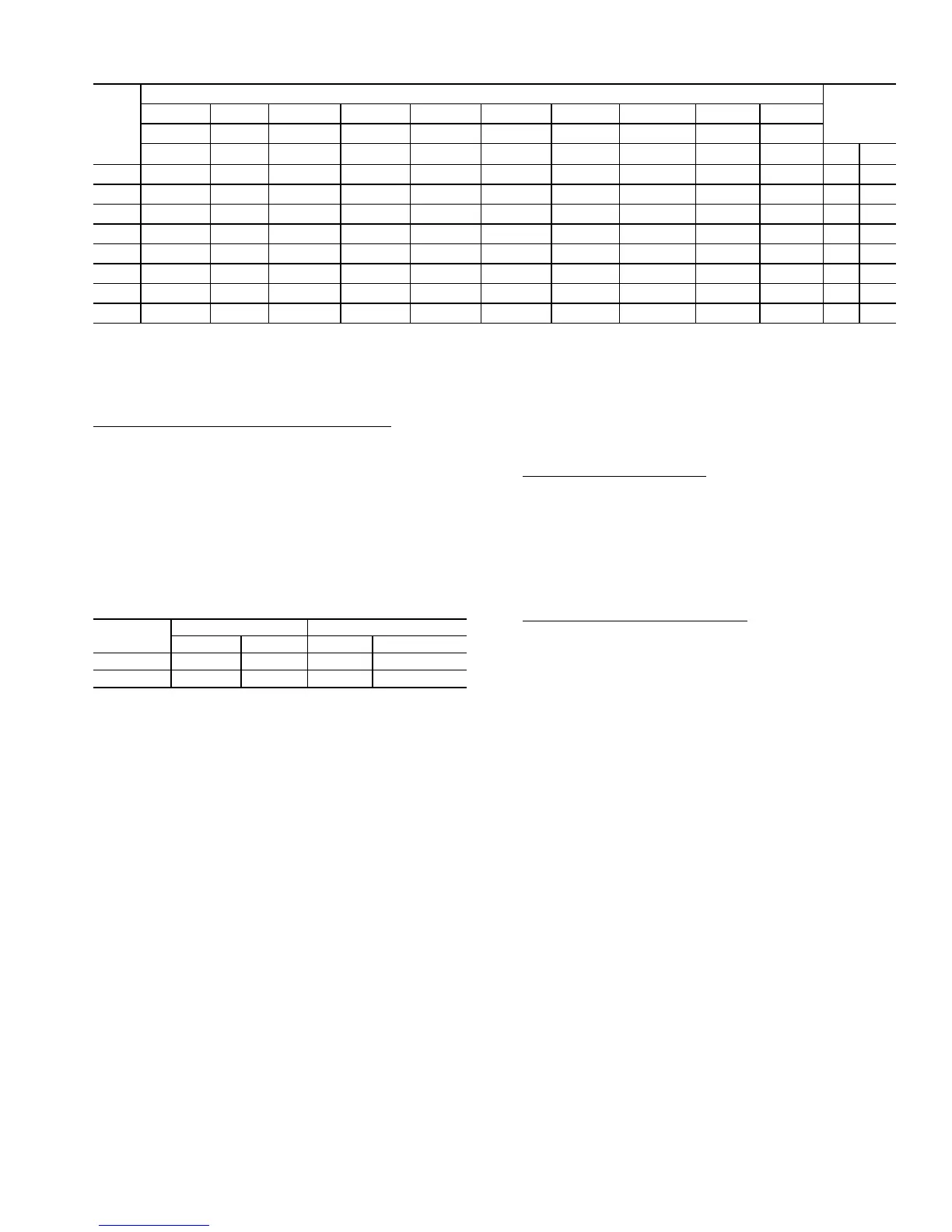
Table 42 — Modulating Gas Heat Control Steps (HT.ST = 3)
* ON when Outputs
HEAT
H1.CP > 54%, OFF when Outputs
HEAT
H1.CP < 46%.
The electric heat outputs are located on the MBB. The ana-
log output that sets the SCR electric heat section capacity is lo-
cated on the SCB.
Limit Switch Temperature Monitoring (
LIM.M) — Variable
air volume applications in the low heat or tempering mode can
experience low airflow and as a result it is possible for nuisance
trips of the gas heat limit switch, thereby shutting off all gas
stages. In order to achieve consistent heating in a tempering
mode, a thermistor (Tempe ratu res
AIR.T
S.G.LS) is placed
next to the limit switch and monitored for overheating. In order
to control a tempering application where the limit switch
temperature has risen above either the upper or lower configu-
ration parameters (SW.L.T, SW.H.T), the staged gas control
will respond by clamping or droping gas stages. See Table 43.
Table 43 — SCR Electric Heat Control Steps
If the Limit Switch Monitoring configuration parameter
(LIM.M) is set to YES, all the modes will be monitored. If set
to NO, then only LAT Cutoff mode and Capacity Clamp mode
for RISE will be monitored.
If S.G.LS rises above SW.L.T or if (LAT – LAT last time
through the capacity calculation) is greater than (RISE)
degrees F per second, the control will not allow the capacity
routine to add stages and will turn on the Capacity Clamp
mode.
If S.G.LS rises above SW.H.T the control will run the capac-
ity routine immediately and drop all heat stages and will turn
on the Limiting mode.
If S.G.LS falls below SW.L.T the control will turn off both
Capacity Clamp mode and Limiting mode with one exception.
If (LAT – LAT last time through the capacity calculation) is
greater than “RISE” degrees F per second, the control will stay
in the Capacity Clamp mode.
If control is in the Limiting mode and then S.G.LS falls
below SW.L.T, and LAT is not rising quickly, the control will
run the capacity calculation routine immediately and allow a
full stage to come back on if desired this first time through
upon recovery. This will effectively override the “max capacity
stage” clamp.
In addition to the above checks, it is also possible at low cfm
for the supply-air temperature to rise and fall radically between
capacity calculations, thereby impacting the limit switch tem-
perature. In the case where supply-air temperature (LAT) rises
above the control point (HT.C.P) + the cutoff point (LAT.L) the
control will run the capacity calculation routine immediately
and drop a stage of heat. Thereafter, every time the capacity
calculation routine runs, provided the control is still in the LAT
cutoff mode condition, a stage will drop each time through.
Falling back below the cutoff point will turn off the LAT cutoff
mode.
CONTROL BOARD INFORMATION
Integrated Gas Control (IGC)
— One IGC is provided with
each bank of gas heat exchangers; 2, 3, 4, or 5 IGC are used de-
pending on unit size and heat capacity. The IGC controls the
direct spark ignition system and monitors the rollout switch,
limit switches, and induced-draft motor Hall Effect switch. For
units equipped with Modulating Gas heat, the IGC in the Mod-
ulating Gas section uses a Pressure Switch in place of the Hall
Effect sensor. The IGC is equipped with a LED (light-emitting
diode) for diagnostics. See Table 44.
Integrated Gas Control Board Logic
— This board provides
control for the ignition system for the gas heat sections.
When a call for gas heat is initiated, power is sent to W on
the IGC boards. For standard 2-stage heat, all boards are wired
in parallel. For modulating gas heat, each board is controlled
separately. When energized, an LED on the IGC board will be
turned on. See Table 44 for LED explanations.
Each board will ensure that the rollout switch and limit
switch are closed. The induced-draft motor is then energized.
For units equipped with 2-stage gas heat the speed of the motor
is proven with a Hall Effect sensor on the motor. For units
equipped with modulating gas heat the motor function is prov-
en with a pressure switch. When the motor speed or function is
proven, the ignition activation period begins. The burners ig-
nite within 5 seconds. If the burners do not light, there is a 22-
second delay before another 5-second attempt is made. If the
burners still do not light, this sequence is repeated for 15 min-
utes. After 15 minutes have elapsed and the burners have not
ignited then heating is locked out. The control will reset when
the request for W (heat) is temporarily removed.
When ignition occurs, the IGC board will continue to moni-
tor the condition of the rollout switch, limit switches, Hall Ef-
fect sensor or pressure switch, and the flame sensor. Forty-five
seconds after ignition has occurred, the IGC will request that
the indoor fan be turned on.
The IGC fan output (IFO) is connected to the indoor fan in-
put on the MBB which will indicate to the controls that the in-
door fan should be turned on (if not already on). If for some
reason the overtemperature limit switch trips prior to the start
of the indoor fan blower, on the next attempt the 45-second de-
lay will be shortened by 5 seconds. Gas will not be interrupted
to the burners and heating will continue. Once modified, the
fan delay will not change back to 45 seconds unless power is
reset to the control.
STAGE
RELAY OUTPUT
CAPACITY
%
Heat 1 Heat 2 Heat 3 Heat 4 Heat 5 Heat 6 Heat 7 Heat 8 Heat 9 Heat 10
MBB-RLY8 TR1-CR SCB-RLY1 SCB-RLY2 SCB-RLY3 SCB-RLY4 MBB-RLY9 MBB-RLY10 CXB-RLY1 CXB-RLY2
IGC1 MGV1 IGC2 MGV2 IGC3 MGV3 IGC4 MGV4 IGC5 MGV5 MIN MAX
0 OFF OFF OFF OFF OFF OFF OFF OFF OFF OFF 0 0
1 ON OFF/ON* OFF OFF OFF OFF OFF OFF OFF OFF 6 20
2 ON OFF/ON* ON OFF OFF OFF OFF OFF OFF OFF 21 35
3 ON OFF/ON* ON OFF ON OFF OFF OFF OFF OFF 36 50
4 ON OFF/ON* ON OFF ON OFF ON OFF OFF OFF 51 65
5 ON OFF/ON* ON OFF ON OFF ON OFF ON OFF 66 80
6 ON OFF/ON* ON ON ON ON ON OFF ON OFF 76 90
7 ON OFF/ON* ON ON ON ON ON ON ON ON 86 100
STAGE
RELAY OUTPUT CAPACITY (%)
Heat1 Heat2 Min. Max.
0OFFOFF0 0
1 ON ON 0 100
 Loading...


