234
APPENDIX G — OPTIONAL MOTORMASTER
®
V CONTROL
GENERAL
This appendix contains instructions for the start-up and ser-
vice of the optional Motormaster V (MMV) control on
48/50N 75-150 ton units.
The Motormaster V control is a motor speed control device
which adjusts condenser fan motor speed in response to an ana-
log signal from the unit ComfortLink controls. A properly ap-
plied Motormaster V control extends the operating range of air-
conditioning systems and permits operation at lower outdoor
ambient temperatures.
Location of Motormaster V device is in the unit power box.
See the power box component arrangement for details.
Configure Motormaster
®
V Control — The
Motormaster V control is configured for analog control mode.
The Motormaster V varies the condenser with an acceptable
head pressure. No additional programming is required. See
Table P.
Table P — Configuration Table
The following ComfortLink control configurations must be
set when using a Motormaster V device:
• Configuration
COOL
M.M. = YES
Test Motormaster V Control — To test the control and
motor, see Service Test section.
START-UP
The Motormaster V electronic control will be powered up
as long as unit voltage is present. When the system calls for
cooling, the Motormaster relay (MMR) will be energized to
initiate the start-up sequence for the Motormaster V electronic
control. The LED (light-emitting diode) will display the speed
of the motor. The display range will be 8 to 60 Hz. The Motor-
master V electronic control will start the condenser fan when
the compressor engages. The ComfortLink controls will adjust
the fan speed via the Motormaster V electronic control to main-
tain approximately 320 psig. Above that pressure, the fan
should operate at full speed.
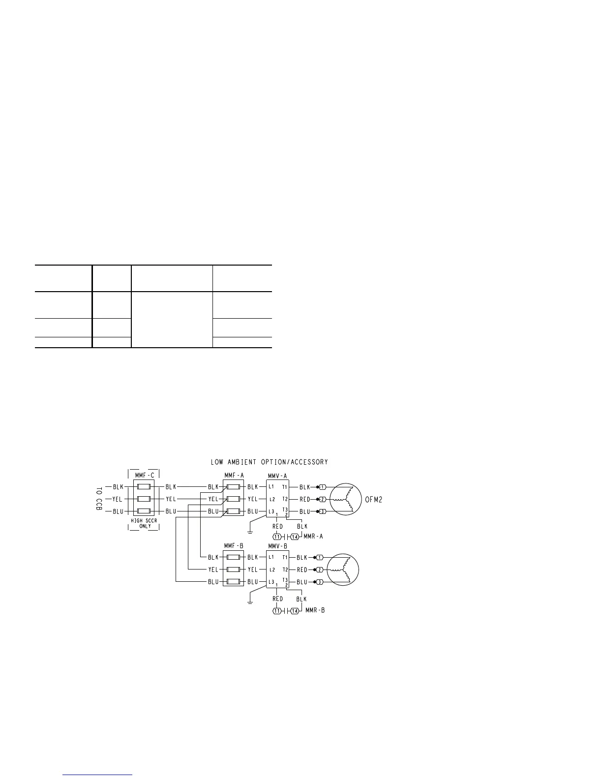
For all units, two Motormaster V devices are used, one for
each circuit. See Fig. M for typical Motormaster V wiring de-
tails. See Static Pressure Control section for details.
No field programming is required. If controller does not
function properly, the information provided in the Trouble-
shooting section can be used to program and troubleshoot the
drive.
NOMINAL
VOLTAGE
(V-Ph-Hz)
MODE
CONTROL INPUT
(Pin 5)
START
CONTACTS
230-3-60
460-3-60
575-3-60
1
Internal PI control,
0-5V feedback
TB 1,2
208-3-60
380-3-60
2 TB 13A,2
400-3-50 4 TB 13C,2
OFM6 (75)
OFM5 (90,105,120 STD-EFF)
OFM8 (90,105,120,130 HI-EFF)
OFM8 (130,150 STD-EFF)
Fig. M — Motormaster
®
V Wiring
LEGEND
CCB — Control Circuit Breaker
MMF — Motormaster V Fuses
MMR — Motormaster V Relay
MMV — Motormaster V Control
OFM — Outdoor-Fan Motor
SCCR — Short Circuit Current Rating
a48-8723
 Loading...


