46
during the occupied state. If AUX.R is set to 3, the auxiliary re-
lay will energize when the supply fan is energized (and, if
equipped with a VFD, the VFD output is not 0%). The default
is 0.
Space Temp Sensor (
SPT.S) — If a space temperature sensor
is installed (T55/T56), enable this configuration.
Space Temp Offset Sensor (
SP.O.S) — If a T56 sensor is in-
stalled with the space temperature offset slider, enable this con-
figuration.
Space Temp Offset Range (
SP.O.R) — If a space tempera-
ture offset sensor is installed, it is possible to configure the
"sweep" range of the slider by adjusting this "range" configura-
tion.
Space Air RH Sensor (
SRH.S) — If a space relative humidity
sensor is installed, enable this configuration.
Return RH Sensor (
RRH.S) — If a return air relative humidi-
ty sensor is installed, enable this configuration.
Mixed RH Sensor (
MRH.S) — If a mixed air relative humid-
ity sensor is installed, enable this configuration.
Cooling Control — The N Series ComfortLink controls
offer two basic control approaches to mechanical cooling:
multi-stage cooling (CV) and multiple stages of cooling (VAV).
In addition, the ComfortLink controls offer the ability to run
multiple stages of cooling for either a space temperature sensor
or thermostat by controlling the unit to either a low or high cool
supply air set point.
SETTING UP THE SYSTEM — The control type (Configu-
ration
UNIT
C.TYP) determines the selection of the type
of cooling control as well as the technique for selecting a cool-
ing mode. Unit staging tables are shown in Appendix C.
NOTE: Whether a unit has a VFD or a supply fan installed for
static pressure control has no effect on configuration of the
machine control type (C.TYP). No matter what the control
type, it is possible to run the unit in either CV or VAV mode
provided there are enough stages to accommodate lower air
volumes for VAV operation. Refer to the section on static pres-
sure control on page 69 for information on how to set up the
unit for the type of supply fan control desired.
Machine Control Type (
Configuration
UNIT
C.TYP) —
The most fundamental cooling control configuration is located
under Configuration
UNIT.
*This default is model number dependent.
This configuration defines the technique and control source
responsible for selecting a cooling mode and in determining the
method by which compressors are staged. The control types
are:
• C.TYP = 1 (VAV-RAT) and C.TYP = 2 ( VAV- S P T )
Both of these configurations refer to standard VAV opera-
tion. If the control is occupied, the supply fan is run continu-
ously and return-air temperature will be used for both in the
determination of the selection of a cooling mode. VAV-SPT
differs from VAV-RAT only in that during the unoccupied
period, space temperature will be used instead of return-air
temperature to start the fan for ten minutes before the re-
turn-air temperature is allowed to call out any mode.
• C.TYP = 3 (TSTAT – MULTI)
This configuration will force the control to monitor the ther-
mostat inputs to make a determination of mode. Unlike tra-
ditional 2-stage thermostat control, the unit is allowed to use
multiple stages of cooling control and perform VAV style
operation. The control will be able to call out a LOW
COOL or a HIGH COOL mode and maintain a low or high
cool supply air set point.
• C.TYP = 4 (SPT – MULTI)
This configuration will force the control to monitor a space
temperature sensor to make a determination of mode. Un-
like traditional 2-stage space temperature control, the unit is
allowed to use multiple stages of cooling control and per-
form VAV style operation. The control will be able to call
out a LOW COOL or a HIGH COOL mode and maintain a
low or high cool supply air set point.
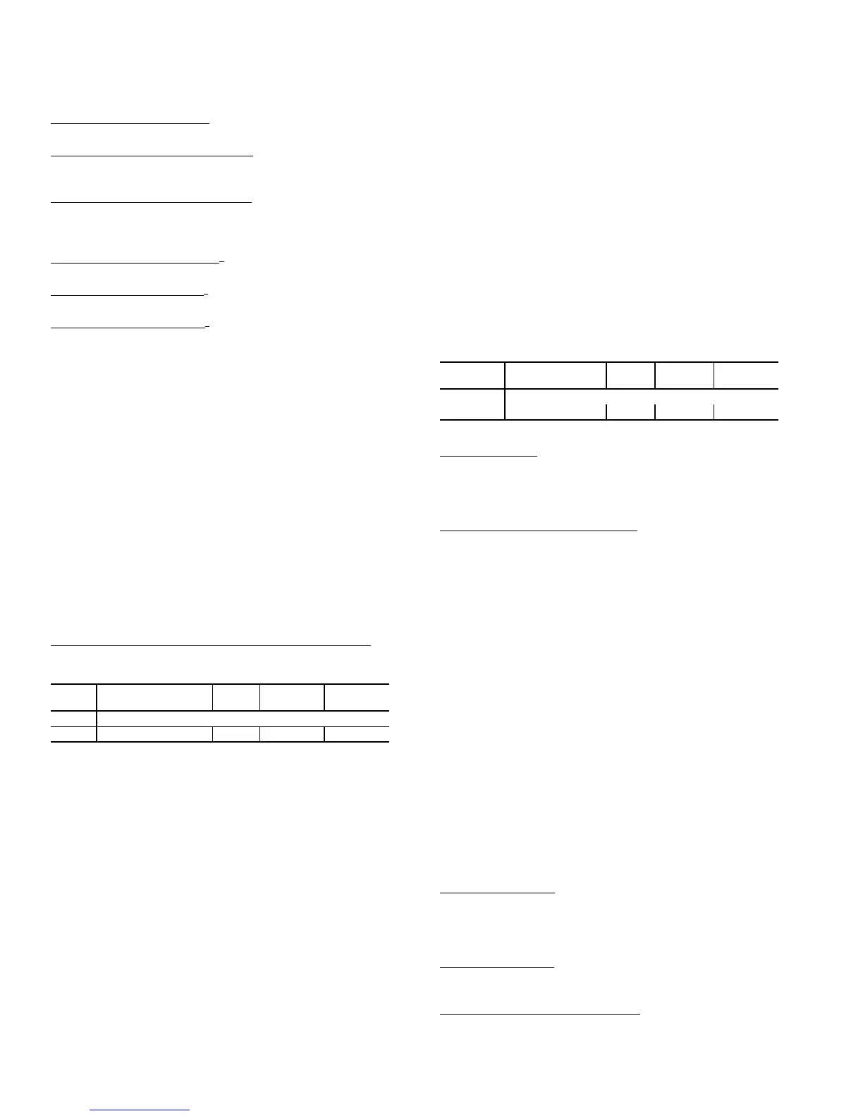
MACHINE DEPENDENT CONFIGURATIONS — Some
configurations are linked to the physical unit and must not be
changed. The configurations are provided in case a field
replacement of a board occurs and the settings are not
preserved by the download process of the new software. The
following configurations apply to all machine control types
(C.TYP). These configurations are located at the local display
under Configuration
UNIT. See Table 26.
Table 26 — Machine Dependent Configurations
*Dependent on unit.
Unit Size (SIZE) — There are 6 unit sizes (tons) for the N Se-
ries control. Make sure this configuration matches the size
called out by the model number of the unit. This is important as
the cooling stage tables are directly determined based on the
SIZE configuration.
EDT Reset Configuration (
RS.CF) — This configuration ap-
plies to several machine control types (Configura-
tion
UNIT
C.TYP = 1,2,3, and 4). See Table 28.
• 0 = NO RESET
No supply air reset is in effect
•1 = SPT RESET
Space temperature will be used as the reset control variable
along with both RTIO and LIMT in the calculation of the
final amount of reset to be applied (Inputs
RSET
SA.S.R).
• 2 = RAT RESET
Return-air temperature will be used as the reset control vari-
able along with both RTIO and LIMT in the calculation of
the final amount of reset to be applied (Inputs
RSET
SA.S.R).
• 3 = 3RD PARTY RESET
The reset value is determined by a 4 to 20 mA third party
input. An input of 4 mA would correspond to 0º F reset. An
input of 20 mA would correspond to 20º F reset. Configur-
ing the control for this option will cause RES.S to become
enabled automatically with the CEM board. To avoid
alarms make sure the CEM board and third party input are
connected first before enabling this option.
Reset Ratio (
RTIO) — This configuration is used when
RS.CF is set to 1 or 2. For every degree that the controlling
temperature (space/return) falls below the occupied cooling set
point (OCSP), the calculated value of the supply air reset will
rise by the number of degrees as specified by this parameter.
Reset Limit (
LIMT) — This configuration is used when
RS.CF is set to 1 or 2. This configuration places a clamp on the
amount of supply air reset that can be applied.
EDT 4-20 mA Reset Input (
RES.S) — This configuration is
automatically enabled when Configuration
EDT.R
RS.CF is set to 3 (third party reset).
ITEM EXPANSION RANGE
CCN
POINT
DEFAULTS
UNIT UNIT CONFIGURATION
C.TYP Machine Control Type 1 - 4 CTRLTYPE *
ITEM EXPANSION RANGE
CCN
POINT
DEFAULTS
UNIT UNIT CONFIGURATION
SIZE Unit Size (75-150) 75-150 UNITSIZE *
 Loading...


