69
TEMPERING MODE — In a vent or cooling mode, the
economizer at minimum position may send extremely cold
outside air down the ductwork of the building. Therefore it
may be necessary to bring heat on to counter-effect this low
supply-air temperature. This is referred to as the tempering
mode.
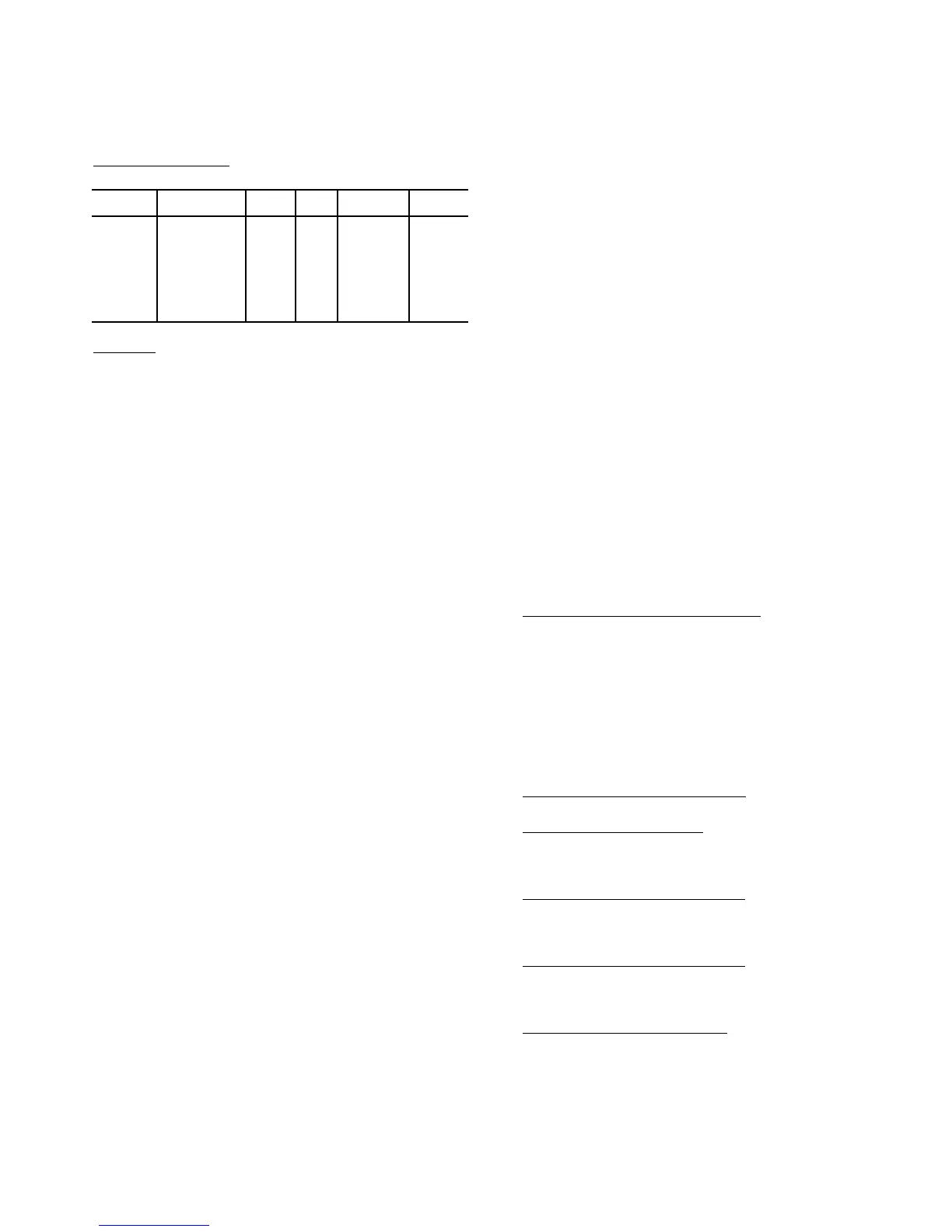
Setting up the System
— The relevant set points for temper-
ing are located at the local display under Setpoints:
Operation
— First, the unit must be in a vent mode, a low cool,
or a high cool HVAC mode to be considered for a tempering
mode. Secondly, the tempering mode is only allowed when the
rooftop is configured for modulating gas, SCR electric heat, or
hydronic heating (Configuration
HEAT
HT.CF=3 or 4).
Also, if OAT is above the chosen tempering set point, temper-
ing will not be allowed. Additionally, tempering mode is
locked out if any stages of mechanical cooling are present.
If the control is configured for staged gas, modulating gas,
SCR electric heat, or hydronic heating and the control is in a
vent, low cool, or high cool HVAC mode, and the rooftop con-
trol is in a situation where the economizer must maintain a
minimum position/minimum cfm, then the evaporator dis-
charge temperature (EDT) will be monitored. If the EDT falls
below a particular trip point then tempering mode may be
called out:
HVAC mode = “Tempering Vent”
HVAC mode = “Tempering LoCool”
HVAC mode = “Tempering HiCool”
The decision making/selection process for the tempering
trip set point is as follows:
If an HVAC cool mode is in effect, then the tempering cool
point is SASP – T.CL.
If not in effect and unit is in a pre-occupied purge mode
(Operating Modes
MODE
IAQ.P=ON), then the trip point
is T.PRG.
If not in effect and unit is in an occupied mode (Operating
Modes
MODE
IAQ.P=ON), then the trip point is
TEMPVOCC.
For all other cases, the trip point is TEMPVUNC.
NOTE: The unoccupied economizer free cooling does not
qualify as a HVAC cool mode as it is an energy saving feature
and has its own OAT lockout already. The unoccupied free
cooling mode (HVAC mode = Unocc. Free Cool) will override
any unoccupied vent mode from triggering a tempering mode.
A minimum amount of time must pass before calling out
any tempering mode. In effect, the EDT must fall below the
trip point value –1° F continuously for a minimum of 2 min-
utes. Also, at the end of a mechanical cooling cycle, a 10-min-
ute delay will be enforced before considering a tempering dur-
ing vent mode in order to allow any residual cooling to dissi-
pate from the evaporator coil.
If the above conditions are met, the algorithm is free to
select the tempering mode (MODETEMP).
If a tempering mode becomes active, the modulating heat
source (staged gas, modulating gas, SCR electric heat, or hot
water) will attempt to maintain leaving-air temperature (LAT)
at the tempering set point used to trigger the tempering mode.
The technique for modulation of set point for staged gas, mod-
ulating gas, SCR electric heat, and hydronic heat is the same as
in a heat mode. More information regarding the operation of
heating can be referenced in the Heating Control section.
Recovery from a tempering mode (MODETEMP) will
occur when the EDT rises above the trip point. On any change
in HVACMODE, the tempering routine will re-assess the tem-
pering set point which may cause the control to continue or exit
tempering mode.
Static Pressure Control — Variable air volume (VAV)
air-conditioning systems must provide varying amounts of air
to the conditioned space. As air terminals downstream of the
unit modulate their flows, the unit must simply maintain con-
trol over duct static pressure in order to accommodate the
needs of the terminals, and therefore to meet the varying com-
bined airflow requirement. The unit design includes an option-
al means of accommodating this requirement. This section de-
scribes the technique by which this control takes place.
A unit intended for use in a VAV system can be equipped
with a variable frequency drive (VFD) for the supply fan. The
speed of the fan can be controlled directly by the ComfortLink
controls. A duct static pressure transducer is located in the aux-
iliary control box. The signal from the pressure sensor is re-
ceived by the RCB board and is then used in a PID control rou-
tine that outputs a fan speed to the VFD.
The PID routine periodically calculates the static pressure
error from set point. This error at any point in time is simply
the duct static pressure set point minus the measured duct stat-
ic. It is the Proportional term of the PID. The routine also cal-
culates the Integral of the error over time, and the Derivative
(rate of change) of the error. A calculated value is then used to
create an output signal used to adjust the VFD to maintain the
static pressure set point.
SETTING UP THE SYSTEM — Here are the options un-
der the Local Display Mode Configuration
SP. See Table 46.
Static Pressure Configuration (
SP.CF) — This variable is
used to configure the use of ComfortLink for static pressure
control. It has the following options:
• 0 (DISABLED) - No static pressure control by Com-
fortLink controls. This would be used for a constant vol-
ume (CV) application when static pressure control is not
required or for a VAV application if there will be third-
party control of the VFD. In this latter case, a suitable
means of control must be field installed.
• 1 (ENABLED) - This will enable the use of ComfortLink
controls
Staged Air Volume Control (
SP.SV) — This variable enabled
the use of a CV unit with VFD for staged air volume control.
Static Pressure Sensor (
SP.S) — This variable enables the use
of a supply duct static pressure sensor. This must be enabled to
use ComfortLink controls for static pressure control. If using a
third-party control for the VFD then this should be disabled.
Static Pressure Low Range (
SP.LO) — This is the minimum
static pressure that the sensor will measure. For most sensors
this will be 0 in. wg. ComfortLink controls will map this value
to a 4 mA sensor output.
Static Pressure High Range (
SP.HI) — This is the maximum
static pressure that the sensor will measure. Commonly this
will be 5 in. wg. The ComfortLink controls will map this value
to a 20 mA sensor output when the signal is 20 mA.
Static Pressure Set Point (
SP.SP) — This is the static pres-
sure control point. It is the point against which ComfortLink
controls compares the actual measured supply duct pressure for
determination of the error that is used for PID control. Adjust
SP.SP to the minimum value necessary for proper operation of
air terminals in the conditioned space at full load and part load.
Too high a value will cause unnecessary fan motor power con-
sumption at part load conditions and/or noise problems. Too
low a value will result in insufficient airflow.
ITEM EXPANSION RANGE UNITS
CCN
POINT
DEFAULT
T.PRG
Tempering
Purge SASP
–20-80 dF TEMPPURG 50
T.CL
Tempering in
Cool Offset
5-75 ^F TEMPCOOL 5
T.V.OC
Tempering Vent
Occ SASP
–20-80 dF TEMPVOCC 65
T.V.UN
Tempering Vent
Unocc. SASP
–20-80 dF TEMPVUNC 50
 Loading...


