70
VFD Minimum Speed (
SP.MN) — This is the minimum
speed for the supply fan VFD. Typically the value is chosen to
maintain a minimum level of ventilation.
NOTE Most VFDs have a built-in minimum speed adjustment
which should be configured fort 0% when using ComfortLink
controls for static pressure control..
VFD Maximum Speed (
SP.MX) — This is the maximum
speed for the supply fan VFD. This is usually set to 100%.
VFD Fire Speed Override (
SP.FS) — This is the speed that
the supply fan VFD will use during the fire modes; pressuriza-
tion, evacuation and purge. This is usually set to 100%.
Static Pressure Reset Configuration (
SP.RS) — This option
is used to configure the static pressure reset function. When
SP.RS = 0, there is no static pressure reset via an analog input.
When SP.RS = 1, there is static pressure reset based on the
CEM 4-20 mA input and ranged from 0 to 3 in. wg. When
SP.RS = 2, there is static pressure reset based on RAT and de-
fined by SP.RT and SP.LM. When SP.RS = 3, there is static
pressure reset based on SPT and defined by SP.RT and SP.LM.
When SP.RS = 4, there is VFD speed control where 0 mA =
0% speed and 20 mA = 100% (SP.MN and SP.MX will over-
ride).
Static Pressure Reset Ratio (
SP.RT) — This option defines
the reset ratio in terms of static pressure versus temperature.
The reset ratio determines how much the static pressure is re-
duced for every degree below set point for RAT or SPT.
Static Pressure Reset Limit (
SP.LM) — This option defines
the maximum amount of static pressure reset that is allowed.
This is sometimes called a "clamp."
NOTE: Resetting static pressure via RAT and SPT is primarily
a constant volume application which utilizes a VFD. The rea-
soning is that there is significant energy savings in slowing
down a supply fan as opposed to running full speed with sup-
ply air reset. Maintaining the supply air set point and slowing
down the fan has the additional benefit of working around
dehumidification concerns.
Static Pressure PID Config (
S.PID) — Static pressure PID
configuration can be accessed under this heading in the Con-
figuration
SP submenu. Under most operating conditions
the control PID factors will not require any adjustment and the
factory defaults should be used. If persistent static pressure
fluctuations are detected, small changes to these factors may
improve performance. Decreasing the factors generally reduce
the responsiveness of the control loop, while increasing the fac-
tors increase its responsiveness. Note the existing settings be-
fore making changes, and seek technical assistance from Carri-
er before making significant changes to these factors.
Static Pressure PID Run Rate (S.PID
SP.TM) — This is the
number of seconds between duct static pressure readings taken
by the ComfortLink PID routine.
Static Pressure Proportional Gain (S.PID
SP.P) — This is
the proportional gain for the static pressure control PID control
loop.
Static Pressure Integral Gain (S.PID
SP.I) — This is the
integral gain for the static pressure control PID control loop.
Static Pressure Derivative Gain (S.PID
SP.D) — This is the
derivative gain for the static pressure control PID control loop.
RELATED POINTS — These points represent static pressure
control and static pressure reset inputs and outputs. See Table 47.
Static Pressure mA (
SP.M) — This variable reflects the value
of the static pressure sensor signal received by ComfortLink
controls. It may in some cases be helpful in troubleshooting.
Static Pressure mA Trim (
SP.M.T) — This input allows a
modest amount of trim to the 4 to 20mA static pressure trans-
ducer signal, and can be used to calibrate a transducer.
Static Pressure Reset (
SP.RS) — This variable reflects the
value of the static pressure reset signal applied from a CCN
system.
Static Pressure Reset mA (
SP.R.M) —This input reflects the
value of the static pressure transducer reset signal applied from
a CCN system.
Static Pressure Reset Sensor (
SP.RS) — This variable can be
configured to allow static pressure reset from a CCN system.
See relevant CCN documentation for additional details.
Supply Fan VFD Speed (
S.VFD) — This output can be used
to check on the actual speed of the VFD. This may be helpful
in some cases for troubleshooting.
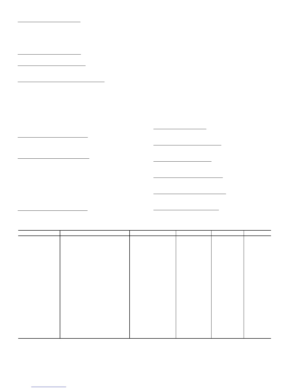
Table 46 — Static Pressure Control Configuration
ITEM EXPANSION RANGE UNITS CCN POINT DEFAULT
SP SUPPLY STATIC PRESS.CFG.
SP.CF Static Pressure Config Enable/Disable STATICFG Disable
SP.SV Staged Air Volume Ctrl Enable/Disable STATICFG Disable
SP.S Static Pressure Sensor Enable/Disable SPSENS Disable
SP.LO Static Press. Low Range –10 - 0 in. W.C. SP_LOW 0
SP.HI Static Press. High Range 0 - 10 in. W.C. SP_HIGH 5
SP.SP Static Pressure Setpoint 0 - 5 in. W.C. SPSP 1.5
SP.MN VFD Minimum Speed 10 - 50 % STATPMIN 20
SP.MX VFD Maximum Speed 50 - 100 % STATPMAX 100
SP.FS VFD Fire Speed Over. 0 - 100 % STATPFSO 100
SP.RS Stat. Pres. Reset Config 0 - 4 SPRSTCFG 0
SP.RT SP Reset Ratio 0 - 2.00 SPRRATIO 0.2
SP.LM SP Reset Limit 0 - 2.00 SPRLIMIT 0.75
SP.EC SP Reset Econo.Position 0 - 100 % ECONOSPR 5
S.PID STAT.PRESS.PID CONFIGS
SP.TM Static Press. PID Run Rate 5 - 120 sec SPIDRATE 15
SP.P Static Press. Prop. Gain 0 - 5 STATP_PG 0.5
SP.I Static Pressure Intg. Gain 0 - 2 STATP_IG 0.5
SP.D Static Pressure Derv. Gain 0 - 5 STATP_DG 0.3
 Loading...


