4
A scheduling function, programmed by the user, controls
the unit occupied/unoccupied schedule. Up to 8 different
schedules can be programmed.
The controls also allow the service person to operate a ser-
vice test so that all the controlled components can be checked
for proper operation.
BASIC CONTROL USAGE
ComfortLink Controls —
The ComfortLink controls
are a comprehensive unit-management system. The control
system is easy to access, configure, diagnose and troubleshoot.
The controls are flexible, providing constant volume and
variable air volume cooling control sequences, and heating
control sequences for two-stage electric and gas systems, mod-
ulating gas heating, SCR (silicon control rectifier) electric heat,
and hydronic heat in both Occupied and Unoccupied schedule
modes. This control also manages:
• VAV duct pressure (VAV units only), with configurable
static pressure reset
• Building pressure through four different power exhaust
schemes
• Return fan applications using fan tracking
• Condenser fan head pressure control
• Dehumidification (with optional reheat) and humidifier
sequences
• Space ventilation control, in Occupied and Unoccupied
periods, using CO
2
sensors or external signals, with ven-
tilation defined by damper position or ventilation airflow
measurement
• Smoke control functions
• Occupancy schedules
• Occupancy or start/stop sequences based on third party
signals
• Alarm status and history and run time data
• Management of a complete unit service test sequence
• Economizer operation and Fault Diagnosis and Detection
(FDD) per California Energy Commission (CEC) Title
24-2013.
System diagnostics are enhanced by the use of sensors for
air and refrigerant temperatures and pressures. Unit-mounted
actuators provide digital feedback data to the unit control.
The ComfortLink controller is cable-ready for connection to
the Carrier Comfort Network
®
(CCN) building management
system. The control provides high-speed communications for
remote monitoring. Multiple 48/50N Series units can be linked
together (and to other ComfortLink controller equipped units)
using a 3-wire communication bus. The unit may be equipped
with optional BACnet communication capability.
The ComfortLink controller is also capable of communicat-
ing with a BACnet network by going through a UPC Open
controller. This permits third-party building management sys-
tems to provide remote monitoring and control of 48/50N
units. See Appendix F for additional information.
The ComfortLink control system is easy to access through
the use of a Navigator™ display. A computer is not needed to
perform unit start-up. The Navigator module provides detailed
explanations of control information.
For service flexibility, a factory-supplied Navigator™ mod-
ule has an extended communication cable that can be plugged
into the unit's communication network either at the main con-
trol box or at the opposite end of the unit, at a remote modular
plug. The Navigator display provides the menu structure, con-
trol access and display data for the unit.
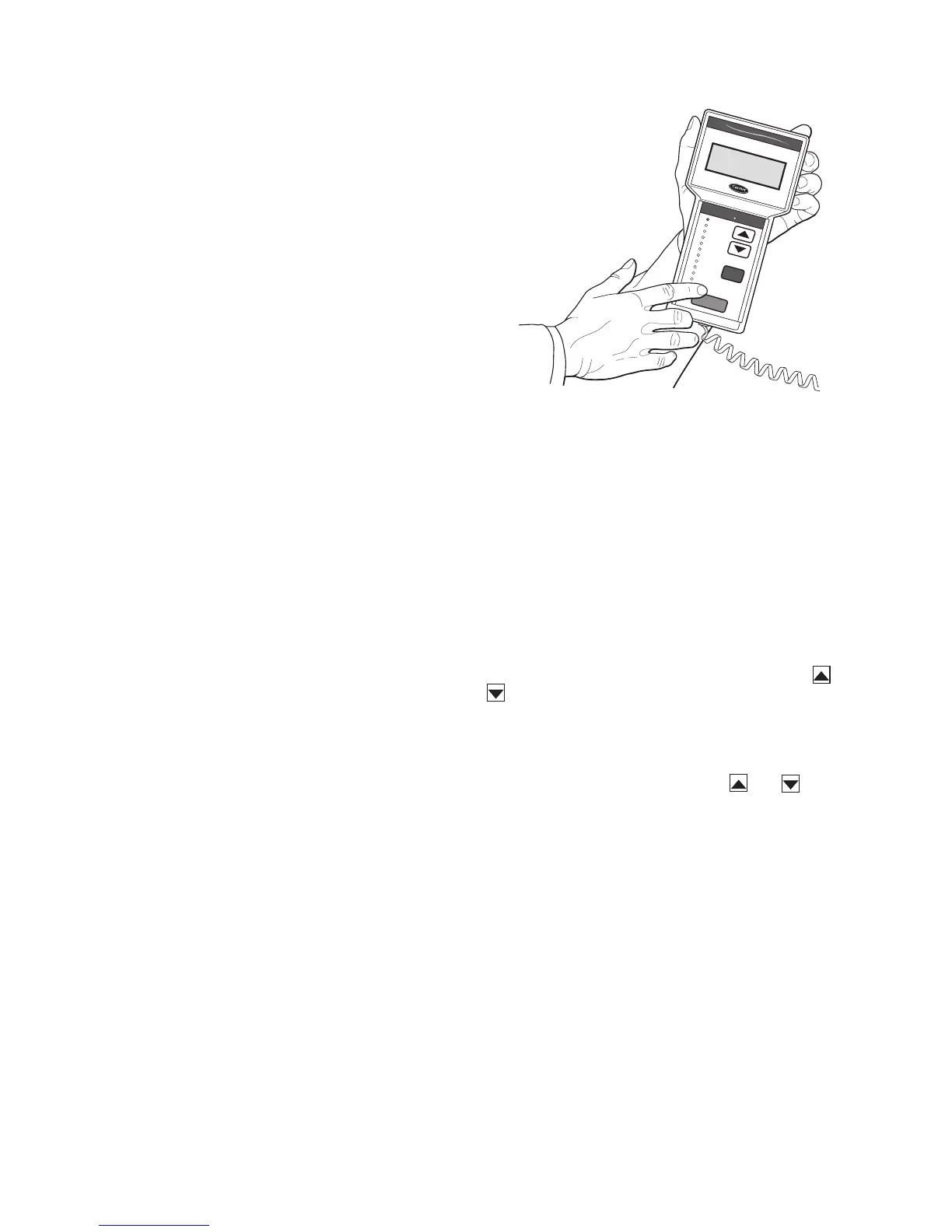
Navigator™ Display — The hand-held Navigator dis-
play is used with the 48/50N Series units. See Fig. 1. The Nav-
igator display is plugged into the RJ-14 jack in the main control
box on the COMM board. The Navigator display can also be
plugged into the RJ-14 jack located on the unit corner post lo-
cated at the economizer end of the unit.
Operation — All units are shipped from the factory with
the Navigator display, which is located in the main control box.
See Fig. 1. The Navigator display provides the user with an in-
terface to the ComfortLink control system. The display has ar-
row keys, an ESC key and an ENTER key. These keys are used
to navigate through the different levels of the display structure.
The Navigator has four lines of display. See Table 2 for the
menu structure.
The four keys are used to navigate through the display
structure, which is organized in a tiered mode structure. See
Table 2 for the first two levels of the mode structure. If the but-
tons have not been used for a period, the display will default to
the AUTO VIEW display category as shown under the RUN
STATUS category. To show the top-level display, press the
ESC key until a blank display is shown. Then use the and
keys to scroll through the top level categories.These are
listed in Appendix A and will be indicated on the Navigator by
the LED next to each mode listed on the face of the display.
When a specific mode or sub-mode is located, push the
ENTER key to enter the mode. Depending on the mode, there
may be additional tiers. Continue to use and keys and
the ENTER key until the desired display item is found. At any
time, the user can move back a mode level by pressing the ESC
key.
Items in the Configuration and Service Test modes are pass-
word protected. The display will prompt for a PASSWORD.
Use the ENTER and arrow keys to enter the four digits of the
password. The default password is 1111.
Pressing the ESC and ENTER keys simultaneously will dis-
play an expanded text description for each display point.
Changing item values or testing outputs is accomplished in
the same manner. Locate and display the desired item. If the
display is in rotating auto-view, press the ENTER key to stop
the display at the desired item. Press the ENTER key again so
that the item value flashes. Use the arrow keys to change the
value or state of an item and press the ENTER key to accept it.
Press the ESC key and the item, value or units display will re-
sume. Repeat the process as required for other items.
If the user needs to force a variable, follow the same process
as when editing a configuration parameter. When using the
Navigator display, a forced variable will be displayed with a
blinking "f" following its value. For example, if supply fan re-
quested (FAN.F ) is forced, the display shows "YESf", where
the "f" is blinking to signify a force on the point. Remove the
Ru
n Sta
tu
s
S
e
rv
ice
Te
s
t
T
em
p
era
ture
s
P
res
s
ure
s
S
e
tpo
in
ts
In
pu
ts
O
utp
uts
C
on
fig
u
ra
tion
T
im
e
Clo
ck
O
p
er
ating
M
od
es
A
la
rm
s
E
N
T
E
R
E
S
C
M
O
D
E
Ala
rm
St a
tus
T
IM
E
E
W
T
L
W
T
S
E
T
P
1
2
.
5
8
5
4
.
6
F
4
4
.1
F
4
4
.
0
F
N
A
V
I
G
A
T
O
R
C
o
m
f
o
r
t
L
in
k
Fig. 1 — Accessory Navigator Display
 Loading...


