172
Filter Drier — Replace whenever the moisture/liquid indi-
cator shows moisture in the system or when the system was
opened for service.
Liquid Line Service Valves — Use caution when
closing liquid line service valves. The expansion of a trapped
liquid can create dangerously high pressures. Remove refriger-
ant immediately from trapped sections or attach a hose from
the high side to the low side of the system to provide relief. If
equipped with a liquid line solenoid valve in the evaporator
section, it will be closed during the off-cycle. This creates the
potential for a liquid trap between the solenoid valve and a
closed service valve. Remove refrigerant immediately from the
section or attach a hose for relief.
Protective Devices
COMPRESSOR PROTECTION
Overcurrent
— Each compressor has one manual reset,
calibrated trip, magnetic circuit breaker. Do not bypass connec-
tions or increase the size of the circuit breaker to correct trou-
ble. Determine the cause and correct it before resetting the
breaker.
Overtemperature
— Each compressor has a protector to pro-
tect it against excessively high discharge gas temperatures.
Additionally, some units contain Copeland compressors
equipped with advanced scroll temperature protection (ASTP).
A label located above the terminal box identifies Copeland
Scroll compressor models that contain this technology. See
Fig. 83. Advanced scroll temperature protection is a form of in-
ternal discharge temperature protection that unloads the scroll
compressor when the internal temperature reaches approxi-
mately 300 F. At this temperature, an internal bi-metal disk
valve opens and causes the scroll elements to separate, which
stops compression. Suction and discharge pressures balance
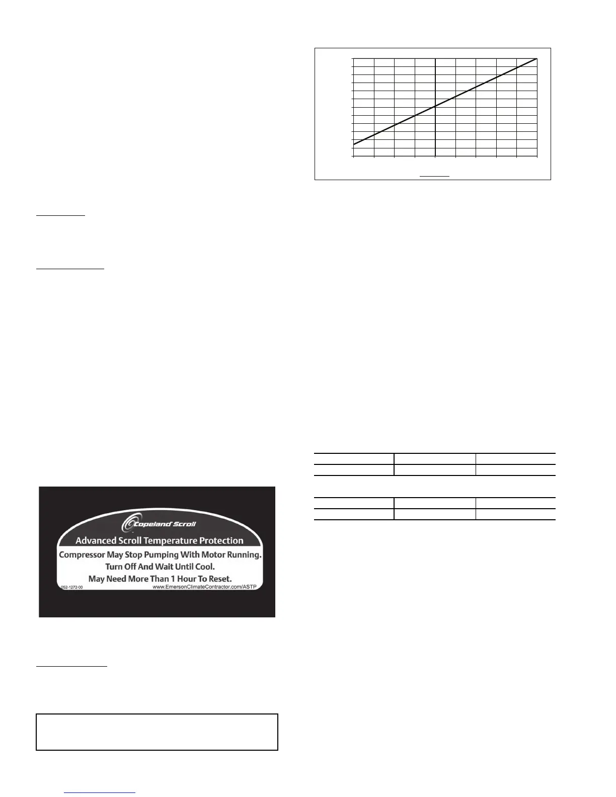
while the motor continues to run. The longer the compressor
runs unloaded, the longer it must cool before the bi-metal disk
resets. See Fig. 84.
To manually reset ASTP, the compressor should be stopped
and allowed to cool. If the compressor is not stopped, the motor
will run until the motor protector trips, which occurs up to
90 minutes later. Advanced scroll temperature protection will
reset automatically before the motor protector resets, which
may take up to 2 hours.
Crankcase Heater
— Each compressor has a crankcase heater
to prevent absorption of liquid refrigerant by oil in the crank-
case when the compressor is idle. Since 115-v power for the
crankcase heaters is drawn from the unit control circuit, main
unit power must be on for the heaters to be energized.
EVAPORATOR-FAN MOTOR PROTECTION — A manu-
al reset, calibrated trip, magnetic circuit breaker protects
against overcurrent. Do not bypass connections or increase the
size of the breaker to correct trouble. Determine the cause and
correct it before resetting the breaker.
CONDENSER-FAN MOTOR PROTECTION — Each
condenser-fan motor is internally protected against over-
temperature. They are also protected against a severe over-
current condition by manual reset, calibrated trip, magnetic cir-
cuit breakers on a common circuit. As with the circuit breakers,
do not bypass connections or increase breaker size to correct
trouble. Determine the cause and correct it before resetting the
breaker.
HIGH-PRESSURE SWITCHES — Settings for these switch-
es are shown in Tables 109 and 110. If either switch trips, that
refrigerant circuit will be automatically locked out by the con-
trols. To reset, set ALARMS
R.CUR = YES.
Table 109 — Pressure Switch Settings (psig)
Table 110 — Pressure Switch Settings (kPa)
Temperature Relief Devices — All units have tem-
perature relief devices to protect against damage from exces-
sive pressures caused by extreme high temperatures (i.e., fire).
These devices protect the high and low side.
Control Circuit, 115 V — This control circuit is protect-
ed against overcurrent by a 10-amp circuit breaker. Breaker can
be reset. If it trips, determine cause of trouble before resetting.
Control Circuit, 24 V — This control circuit is protected
against overcurrent by two 10-amp and four 3.2-amp circuit
breakers. Breakers can be reset. If a breaker trips, determine
cause of trouble before resetting.
Gas Heat (48N Only)
LIMIT SWITCHES — The maximum supply-air temperature
is controlled by a limit switch located in the gas section. The
limit is designed to trip at 100 F above the maximum tempera-
ture rise.
When the limit trips, 2 flashes occur on the IGC board. The
gas valve is de-energized. After cooling, the system will reset
and fires gas again. If four trips occur, the system shuts down
into Lockout and 4 flashes occur on the IGC board. The system
IMPORTANT: After a prolonged shutdown or service
job, energize the crankcase heaters for 24 hours before
starting the compressor.
Fig. 83 — Advanced Scroll Temperature
Protection Label
SWITCH CUTOUT CUT-IN
High 650 10 500 15
SWITCH CUTOUT CUT-IN
High 4482 69 3447 103
0
10
20
30
40
50
60
70
80
90
100
110
120
0 102030405060708090
Compressor Unloaded Run Time (Minutes)
Recommended Cooling Time
(Minutes)
*Times are approximate.
NOTE: Various factors, including high humidity, high ambient tem-
perature, and the presence of a sound blanket will increase cool-
down times.
Fig. 84 — Recommended Minimum Cool-Down
Time After Compressor is Stopped*
 Loading...


