96
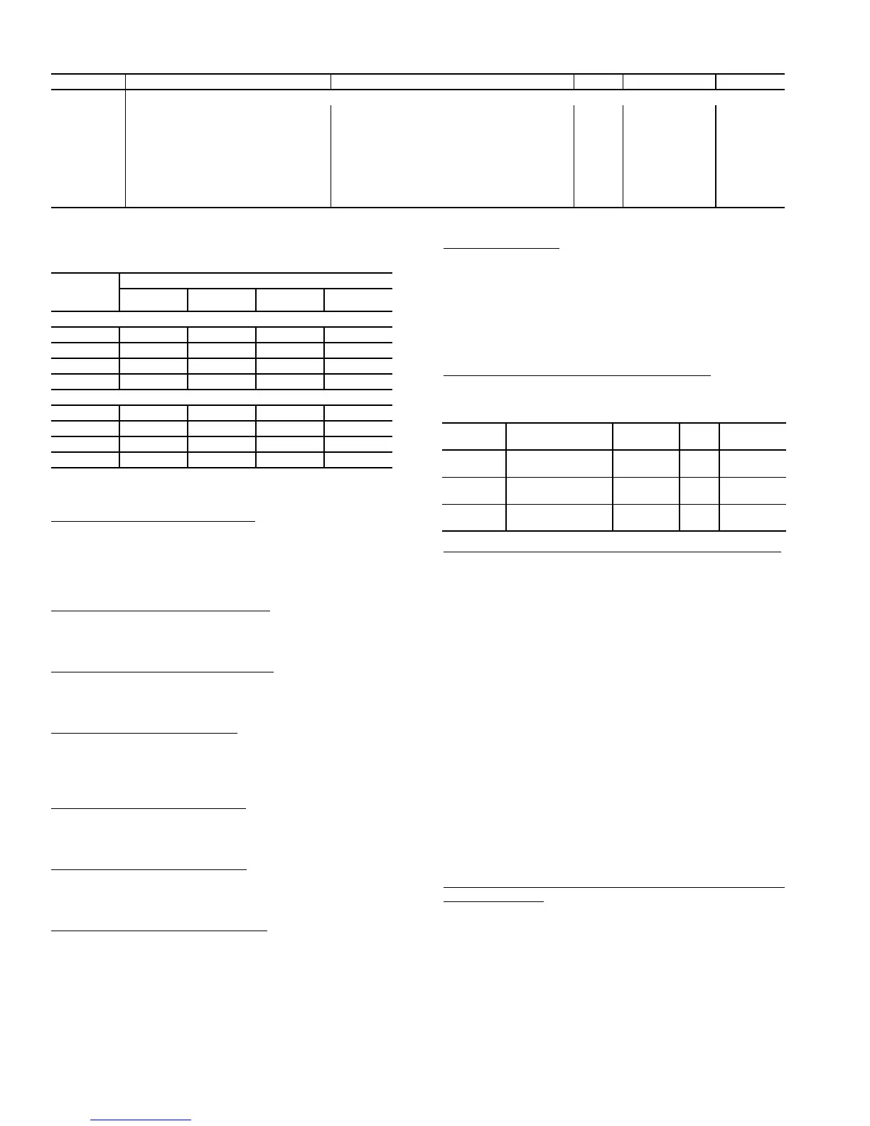
Table 67 — Exhaust Fan VFD Configuration
*This default is model number dependent.
Table 68 — Optional VFD Power Exhaust (PE)
Motor Limitations (FLA)
Power to the VFD must be cycled in order for a change to
this configuration to take effect.
VFD2 Nominal Motor Freq (
N.FRQ) — This configuration
defines the nominal motor frequency. This value must equal
the value on the motor rating plate. This value sets the
frequency at which the output voltage equals the Nominal Mo-
tor Volts (N.VLT). Power to the VFD must be cycled in order
for a change to this configuration to take effect.
VFD2 Nominal Motor RPM (
N.RPM) — This configura-
tion defines the nominal motor speed. This value must equal
the value on the motor rating plate. Power to the VFD must be
cycled in order for a change to this configuration to take effect.
VFD2 Nominal Motor HPwr (
N.PWR) — This configura-
tion defines the nominal motor power. This value must equal
the value on the motor rating plate. Power to the VFD must be
cycled in order for a change to this configuration to take effect.
VFD2 Motor Direction (
M.DIR) — This configuration sets
the direction of motor rotation. Motor direction change occurs
immediately upon a change to this configuration. Power to the
VFD need NOT be cycled for a change to this configuration to
take effect.
VFD2 Acceleration Time (
ACCL) — This configuration sets
the acceleration time from zero to maximum output frequency.
Power to the VFD must be cycled in order for a change to this
configuration to take effect.
VFD2 Deceleration Time (
DECL) — This configuration sets
the deceleration time from maximum output frequency to zero.
Power to the VFD must be cycled in order for a change to this
configuration to take effect.
VFD2 Switching Frequency (
SW.FQ) — This configuration
sets the switching frequency for the drive. Power to the VFD
must be cycled in order for a change to this configuration to
take effect.
VFD2 Type (
TYPE) — This configuration sets the type of
VFD communication. This configuration should not be
changed without first consulting a Carrier service engineering
representative.
Remote Control Switch Input — The remote switch
input is located on the RXB board and connected to TB201
terminals 3 and 4. The switch can be used for several remote
control functions. See Table 69.
Remote Input State
(Inputs
GEN.I
REMT) — This is
the actual real time state of the remote input.
Table 69 — Remote Switch Configuration
Remote Switch Config
(Configuration
UNIT
RM.CF)
— This is the configuration that allows the user to assign dif-
ferent types of functionality to the remote discrete input.
• 0 — NO REMOTE SW — The remote switch will not be
used.
• 1 — OCC-UNOCC SW — The remote switch input will
control the occupancy state. When the remote switch
input is ON, the unit will forced into the occupied mode.
When the remote switch is OFF, the unit will be forced
into the unoccupied mode.
• 2 — STRT/STOP — The remote switch input will start
and stop the unit. When the unit is commanded to stop,
any timeguards in place on compressors will be honored
first. When the remote switch is ON, the unit will be
commanded to stop. When the remote switch is OFF the
unit will be enabled to operate.
• 3 — OVERRIDE SW — The remote switch can be used
to override any internal or external time schedule being
used by the control and force the unit into an occupied
mode when the remote input state is ON. When the
remote switch is ON, the unit will be forced into an occu-
pied state. When the remote switch is OFF, the unit will
use its internal or external time schedules.
Remote Switch Logic Configuration
(Configuration
SW.LG
RMI.L) — The control allows for the configuration
of a normally open/closed status of the remote input switch via
RMI.L. If this variable is configured OPEN, then when the
switch is open, the remote input switch perceives the logic state
as OFF. Correspondingly, if RMI.L is set to CLOSED, the re-
mote input switch will perceive a closed switch as meaning
OFF. See Table 70.
ITEM EXPANSION RANGE UNITS CCN POINT DEFAULTS
E.VFD EXHAUST FAN VFD CONFIG
N.VLT VFD2 Nominal Motor Volts 0 to 999 Volts VFD2NVLT 460*
N.AMP VFD2 Nominal Motor Amps 0 to 999 Amps VFD2NAMP 28.7*
N.FRQ VFD2 Nominal Motor Freq 10 to 500 Hz VFD2NFRQ 60
N.RPM VFD2 Nominal Motor RPM 50 to 30000 RPM VFD2NRPM 1750
N.PWR VFD2 Nominal Motor HPwr 0 to 500 H.P. VFD2NPWR 20*
M.DIR VFD2 Motor Direction 0=FWD, 1=REV VFD2MDIR 0
ACCL VFD2 Acceleration Time 0 to 1800 sec VFD2ACCL 30
DECL VFD2 Deceleration Time 0 to 1800 sec VFD2DECL 30
SW.FQ VFD2 Switching Frequency 0=1kHz, 1=4kHz, 2=8kHz, 3=12kHz VFD2SWFQ 2
Power
Exhaust
HP
UNIT VOLTAGE
208/230 380 460 575
High Efficiency PE
6 7.6 10.0 20.4 9.6
10 10.2 18.2 30.6 12.8
15 15.6 24.4 44.8 19.4
20 20.6 32.4 58.6 26.8
Premium Eficiency PE
6 — — 16.0 8.0
10 — — 29.4 13.6
15 — — 43.0 19.4
20 — — 56.0 25.2
ITEM EXPANSION RANGE UNITS
CCN
POINT
REMT Remote
Input State
ON/OFF RMTIN
RM.CF Remote Switch
Config
0 - 3 RMTINCFG
RMI.L RemSw
Off-Unoc-Strt-NoOv
Open/Close RMTINLOG
 Loading...


