73
2 = Schedule
— Filter configuration for either main or post fil-
ter can be set to 2 (Schedule). In this mode the filter status is
based on a schedule set by the user. The status is determined by
the amount of time remaining in the filter life. The user sets the
lifetime for the filter in months from 1 to 60 (5 years). The de-
fault for this parameter is 12 months. It is also possible to set a
reminder and reset the schedule.
The main and post filters use "Birth points" and current date
to calculate filter life and filter reminder. The birth date and cur-
rent date are expressed as the number of days since 1/1/2000.
To change the main filter life use Configura-
tion
IAQ
FLTC
MF.LT and set to required filter life from
1 to 60 months. To change the post filter life use Configura-
tion
IAQ
FLTC
PF.LT and set to required filter life from
1 to 60 months.
To set main filter life reminder use
Configura-
tion
IAQ
FLTC
MF.RM
and enter required filter reminder
from 0 to 60 months. To set post filter life reminder use
Configu-
ration
IAQ
FLTC
PF.RM
and enter required filter re-
minder from 0 to 60 months. Setting the reminder for either main
or post filter to 0 will disable the reminder function for that filter.
To reset the main filter status schedule use Configura-
tion
IAQ
FLTC
MF.RS, when set to 'yes' the birth date
for the main filter will be converted to the current date in num-
ber of days since 1/1/2000. To reset the post filter status sched-
ule use Configuration
IAQ
FLTC
PF.RS, when set to
'yes' the birth date for the post filter will be converted to the cur-
rent date in number of days since 1/1/2000.
3 = Delta Pressure
— Main and post filter status can be deter-
mined in relation to a maximum pressure differential across the
corresponding filter. The pressure difference is provided by a
transducer and sensors. The delta pressure configuration is dis-
abled in Service Test mode and when the supply fan is not com-
manded on. If the fan is on, the unit is not in test mode and the
filter delta pressure is greater than or equal to the filter final re-
sistance (MF_FR, PF_FR) for a period of time equal to the sta-
tus fault timer (FS.FT) then an alarm will be generated. Recov-
ery from this alert is possible by clearing all alarms or by replac-
ing the dirty filter and the delta pressure is less than the new
filters final resistance for more than 30 seconds.
4 = Predictive Life (Calculate and Learn)
— The filter status
can be determined through a predicted life. When clean filters
are first installed using this configuration they must be commis-
sioned before use. This is done by setting the supply fan to a cer-
tain speed (in %) and measuring Supply Air CFM (SACFM)
versus delta pressure (MF.DP or PF.DP) across the filter. There
will need to be a maximum of 10 entries plus an entry for 0
SACFM and one for maximum SACFM. The data is collected
and stored by the control.
The 10 entries are separated into bins based on maximum
Supply Air CFM (SACFM). Maximum SACFM is based on
unit size and supply fan SACFM configuration (SCFM_CFG)
view Table 51.
Table 51 — Maximum SACFM
During runtime the SACFM is used to interpolate the base-
line pressure. The interpolation is then used to calculate the filter
status. See Table 52.
It is possible to reset the main filter predictive life table and the
post filter predictive life table separately. To reset the main filter
predictive life table use
Configuration
IAQ
FLTC
MFT.R
and select yes. To reset the post filter predictive life table use
Con-
figuration
IAQ
FLTC
PFT.R
and select yes.
5 = Predictive Life (Calculate only) — Once the control has
learned the life of the filter it is possible to set the control to use
the learned information to calculate the life of filters used in the
future. This is only an option when the replacement filters used
are the same type and final resistance as the filters used to learn
the life.
Table 52 — Dirty Filter Switch Points
Economizer — The N Series economizer damper is con-
trolled by communicating actuators motor over the local equip-
ment network (LEN) and is connected directly to linkage in the
economizer section.
Economizers are used to provide ventilation air as well as
free cooling based on several configuration options. This sec-
tion shall be devoted to a description of the economizer and its
ability to provide free cooling. Please see the section on Indoor
Air Quality for more information on setting up and using the
economizer to perform demand controlled ventilation (DCV)
via the controlling of its minimum position. Also, please see
the Third Party Control interface section for a description on
how to take over the operation of the economizer through ex-
ternal control.
The N Series controls have the capability to not only con-
trol an economizer but also to report its health and operation
both to the local display and CCN network. Also, through ei-
ther the local display or the CCN, the service technician has ad-
ditional diagnostic tools at his/her disposal to predict the state
of the economizer.
ECONOMIZER FAULT DETECTION AND DIAGNOS-
TICS (FDD) CONTROL — The Economizer Fault Detection
and Diagnostics control can be divided into two tests: test for
mechanically disconnected actuator and test for stuck/jammed
actuator.
Mechanically Disconnected Actuator
— The test for a me-
chanically disconnected actuator shall be performed by moni-
toring SAT as the actuator position changes and the damper
blades modulate. As the damper opens, it is expected SAT will
drop and approach OAT when the damper is at 100%. As the
damper closes, it is expected SAT will rise and approach RAT
when the damper is at 0%. The basic test shall be as follows:
1. With supply fan running take a sample of SAT at current
actuator position.
2. Modulate actuator to new position.
3. Allow time for SAT to stabilize at new position.
4. Take sample of SAT at new actuator position and deter-
mine:
a. If damper has opened, SAT should have decreased.
b. If damper has closed, SAT should have increased.
5. Use current SAT and actuator position as samples for next
comparison after next actuator move.
UNIT SIZE SCFM_CFG MAX_SACFM
75, 90, 105
LOW FAN 40,000
120, 130, 150
LOW FAN 50,000
75, 90, 105, 120, 130, 150
HIGH FAN 60,000
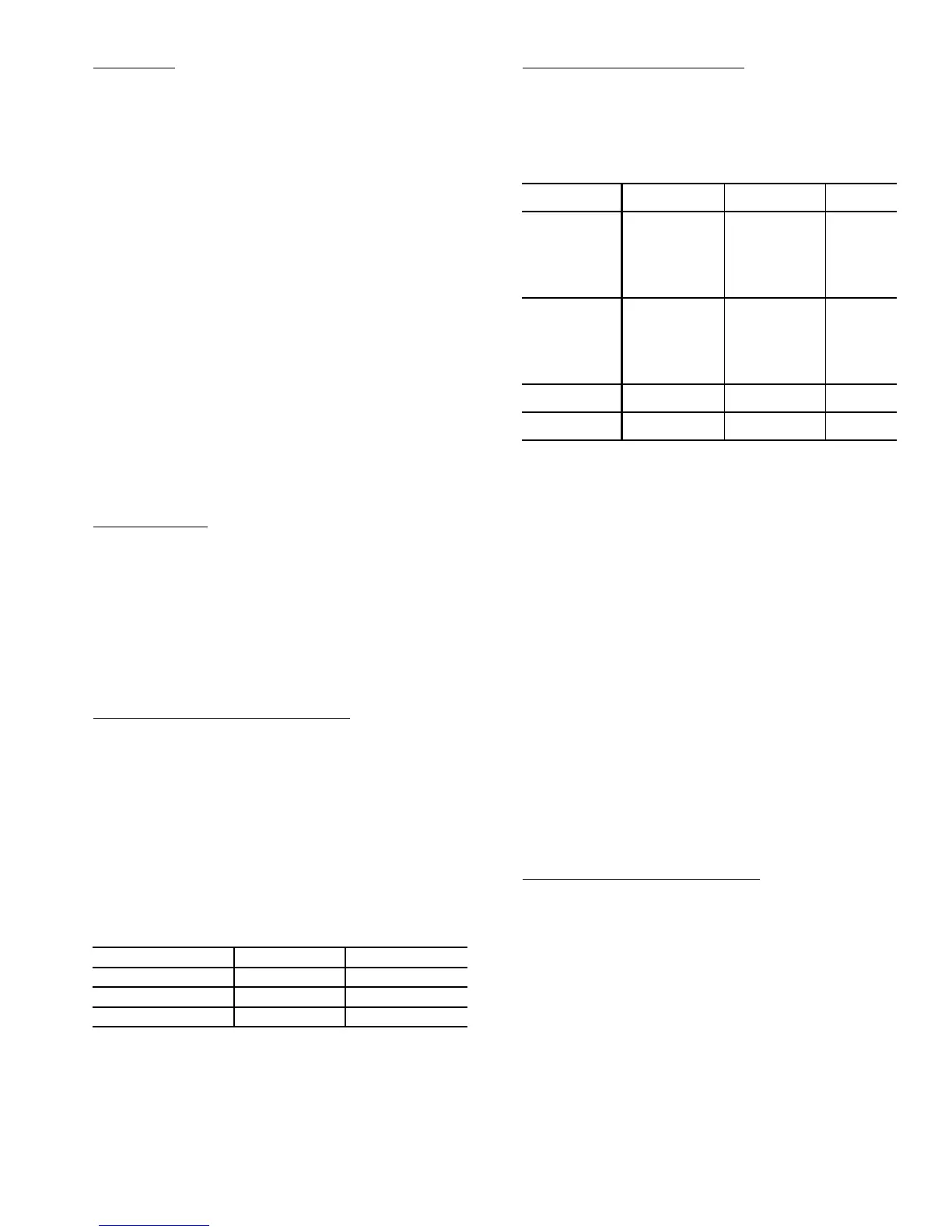
ITEM EXPANSION RANGE
CCN
POINT
Configuration
FLTC
MFL.S
Main Filter Status
Configuration
0 - Disable
1 - S w i t c h
2 - Schedule
3 - Delta Pressure
4 - Calculate and
Learn
5 - Calculate Only
FLTS_ENA
Configuration
FLTC
PFL.S
Post Filter Status
Configuration
0 - Disable
1 - S w i t c h
2 - Schedule
3 - Delta Pressure
4 - Calculate and
Learn
5 - Calculate Only
PFLS_ENA
Inputs
GEN.I
FLT.S
Filter Status Input DRTY/CLN FLTS
Inputs
GEN.I
PFL.S
Filter Status Input DRTY/CLN PFLTS
 Loading...


