64
Hydronic Heating Logic
If the HVAC mode is LOW HEAT:
• The control will command the supply fan on
• The control will modulate the hot water or steam coil
actuator to the heating control point (Run Sta-
tus
VIEW
HT.C.P). The heating control point for
hydronic heat is the heating supply air set point (Set-
points
SA.HT).
If the HVAC mode is HIGH HEAT:
• The control will command the supply fan on
• The control will command the hot water coil actuator to
100%.
Hydronic Heating PID Process
— If the HVAC mode is
LOW HEAT, then the hydronic heating actuator will modulate
to the heating control point (Run Status
VIEW
HT.C.P).
Control is performed with a generic PID loop where:
Error = Heating Control Point (HT.C.P) – Leaving Air Tem-
perature (LAT)
The PID terms are calculated as follows:
P = K * HW.P * error
I = K * HW.I * error + “I” last time through
D = K * HW.D * (error – error last time through)
Where K = HW.TM/60 to normalize the effect of changing the
run time rate.
NOTE: The PID values should be not be modified without
approval from Carrier.
Freeze Status Switch Logic (
Inputs
GEN.I
FRZ.S) — If
the freezestat input (FRZ) alarms, indicating that the coil is
freezing, normal heat control is overridden and the following
actions will be taken:
1. Command the hot water coil actuator to 100%.
2. Command the economizer damper to 0%.
3. Command the supply fan on.
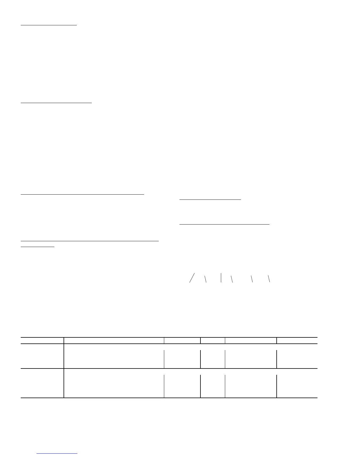
Configuring Hydronic Heat to Communicate Via Actuator
Serial Number — Every actuator used in the N Series control
system has its own unique serial number. The rooftop control
uses this serial number to communicate with the actuator.
These serial numbers are programmed at the factory and
should not need changing. Should field replacement of an actu-
ator become necessary, it will be required to configure the seri-
al numbers of the new actuator. Four individual numbers make
up this serial number and these can be programmed to match
the serial number of the actuator in its Hydronic Heating Actu-
ator Configs group, ACT.C (SN.1, SN.2, SN.3, SN.4). See
Fig. 15.
NOTE: The serial numbers for all actuators can be found
inside the control doors of the unit as well as on the actuator
itself. If an actuator is replaced in the field, it is a good idea to
remove the additional peel off serial number sticker on the
actuator and cover up the old one inside the control doors.
MODULATING GAS HEAT CONTROL (HT.CF = 3 and
HT.ST = 0, 1, 2, or 3) — As an option, the units with gas heat
can be equipped with modulating gas heat controls that will
provide infinite stages of heat capacity. This is intended for
tempering mode and tempering economizer air when in a cool-
ing mode and the dampers are at minimum vent position. Tem-
pering can also be used during a pre-occupancy purge to pre-
vent low temperature air from being delivered to the space.
Tempering for staged gas, modulating gas, and hydronic heat
will be discussed in its own section. This section will focus on
heat mode control, which ultimately is relevant to tempering,
minus the consideration of the supply air heating control point.
The modulating gas and SCR electric heat configurations
are located at the local display under Configura-
tion
HEAT
SG.CF. See Table 37.
SCR ELECTRIC HEAT CONTROL (HT.CF = 5, no req.
set HT.ST) — As an option, the units with electric heat can be
equipped with modulating SCR electric heater controls that
will provide infinite stages of heat capacity. This is intended for
tempering mode and tempering economizer air when in a cool-
ing mode and the dampers are at minimum vent position. Tem-
pering can also be used during a pre-occupancy purge to pre-
vent low temperature air from being delivered to the space.
Tempering for modulating gas, hydronic and SCR electric heat
will be discussed in its own section. This section will focus on
heat mode control, which ultimately is relevant to tempering,
minus the consideration of the supply air heating control point.
Staged Heat Type (
HT.ST) — This configuration instructs the
control as to how many stages and in what order they are
staged. Setting HT.ST = 0, 1, 2, or 3 configures the unit for
Modulating Gas Heat.
Max Cap Change per Cycle (
CAP.M) — This configura-
tion limits the maximum change in capacity per PID run time
cycle.
Table 36 — Hydronic Heat Configuration
00850 - 30063 - 084 -083
ACTUATOR SERIAL NUMBER
{
NOT
USED
{
SN.1
{
{
SN.2 SN.3
{
NOT
USED
{
SN.4
SN.1 = 850
SN.2 = 3
SN.3 = 63
SN.4 = 83
Fig. 15 — Actuator Serial Number Configuration
a48-8507
ITEM EXPANSION RANGE UNITS CCN POINT DEFAULT
HH.CF HYDRONIC HEAT CONFIGS
HW.P Hydronic Ctl.Prop. Gain 0 - 1.5 HW_PGAIN 1
HW.I Hydronic Ctl.Integ. Gain 0 - 1.5 HW_IGAIN 1
HW.D Hydronic Ctl.Derv. Gain 0 - 1.5 HW_DGAIN 1
HW.TM Hydronic PID Rate Config 15 - 300 sec HOTWPIDR 90
ACT.C HYDR.HEAT ACTUATOR CFGS.
SN.1 Hydronic Ht.Serial Num.1 0 - 9999 HTCL_SN1 0
SN.2 Hydronic Ht.Serial Num.2 0 - 6 HTCL_SN2 0
SN.3 Hydronic Ht.Serial Num.3 0 - 9999 HTCL_SN3 0
SN.4 Hydronic Ht.Serial Num.4 0 - 254 HTCL_SN4 0
C.A.LM Hydr.Ht.Ctl.Ang.Lo Limit 0-90 HTCLCALM 85
 Loading...


