2-7
2
2
2
3
4
5
6
7
8
9
10
11
12
13
14
15
16
17
18
18
18
18
18
18
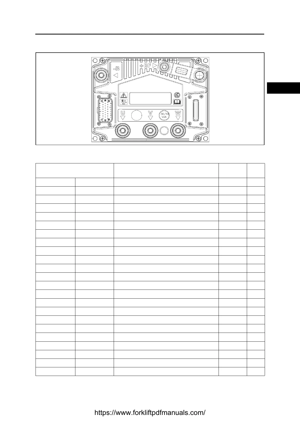
LIFTING LOGIC UNIT
Basic conditions (battery plug connected, key switch ON).
See the reference names of the connectors in the electrical diagram.
CN (pin-colour) ⇔ CN (pin-colour)
From ⇔ To
Description Standard Notes
JP (1-R04) J50 (2-R04) Input +V key +Vb
JP (2) --- Unused
JP (3) --- Unused
JP (4-R04) J50 (2-R04) Input +V key +Vb
JP (5) --- Unused
JP (6-BZ) J50 (12-BZ) Seat microswitch input
JP (7-AV) J13 (3-AV) Pump motor encoder input channel A 0 - 12V
JP (8-AZ) J13 (1-AZ) Output +V pump motor encoder +12 V
JP (9-NZ) J50 (14-NZ) Negative input GND
JP (10) --- Unused
JP (11-NZ) J50 (14-NZ) Negative input GND
JP (12) --- Unused
JP (13) --- Unused
JP (14-HV) J13( 4-HV) Pump motor encoder input channel B 0 - 12V
JP (15-GN) J13( 2-GN) Pump motor encoder negative output GND
JP (16) --- Unused
JP (17) --- Unused
JP (18) --- Unused
JP (19-LV) JT (11-LV) SAFETY IN GND
JP (20-HG) --- CAN-BUS LOW
JP (21-AN) --- CAN-BUS HIGH
JP (22-CN) J3 (2-CN) Output +V pump motor temp. sensor
JP (23-RV) J3 (1-RV) Pump motor temp. sensor negative output GND
https://www.forkliftpdfmanuals.com/
 Loading...
