2-15
2
2
2
3
4
5
6
7
8
9
10
11
12
13
14
15
16
17
18
18
18
18
18
18
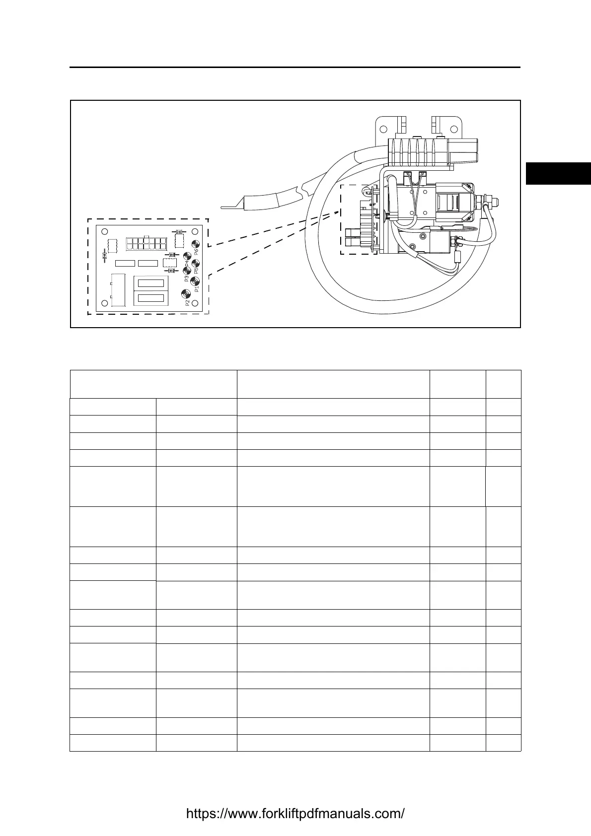
CONTACTOR GROUP
Basic conditions (battery plug connected, key switch ON).
See the reference names of the connectors in the electrical diagram.
CN (pin-colour) ⇔ CN (pin-colour)
From ⇔ To
Description Standard Notes
J50 (1-Z) JT (16-Z) Contactor CT2 negative input GND
J50 (2-R04) J50 (4-R02) Relay US3 power input +Vb
J50 (3-N) --- Negative GND
J50 (4-R02) J21 (1-R02) Output + V key +Vb
J50 (5-R07)
J40 (20-R07)
J40 (21-R07)
J34 (24-R07)
I/O board auxiliary power output +Vb
J50 (6-R07)
J40 (20-R07)
J40 (21-R07)
J34 (24-R07)
I/O board auxiliary power output +Vb
J50 (7-NL) J20 (1-NL) Seat micro signal input
J50 (8-Z) JT (17-Z) Input + V contactor CT2 +Vb
J50 (9-AB)
J71 (2-AB)
J137 (13-AB)
Alarms buzzer negative output GND
J50 (10-NZ) J34 (14-NZ) Parking brake signal
J50 (11-L) --- Negative GND
J50 (12-BZ)
JT (6-BZ)
JP (6-BZ)
Seat microswitch signal
J50 (13-BV) J30 (3-BV) Parking brake microswitch output
J50 (14-NZ)
JP (9-NZ)
JP (11-NZ)
Negative GND
J52 (1-R09) J90 (1-R09) OPT fuse holder power output +Vb
J52 (2-R08) J107/A (1-R08) Heater power output +Vb
https://www.forkliftpdfmanuals.com/
 Loading...
