2-8
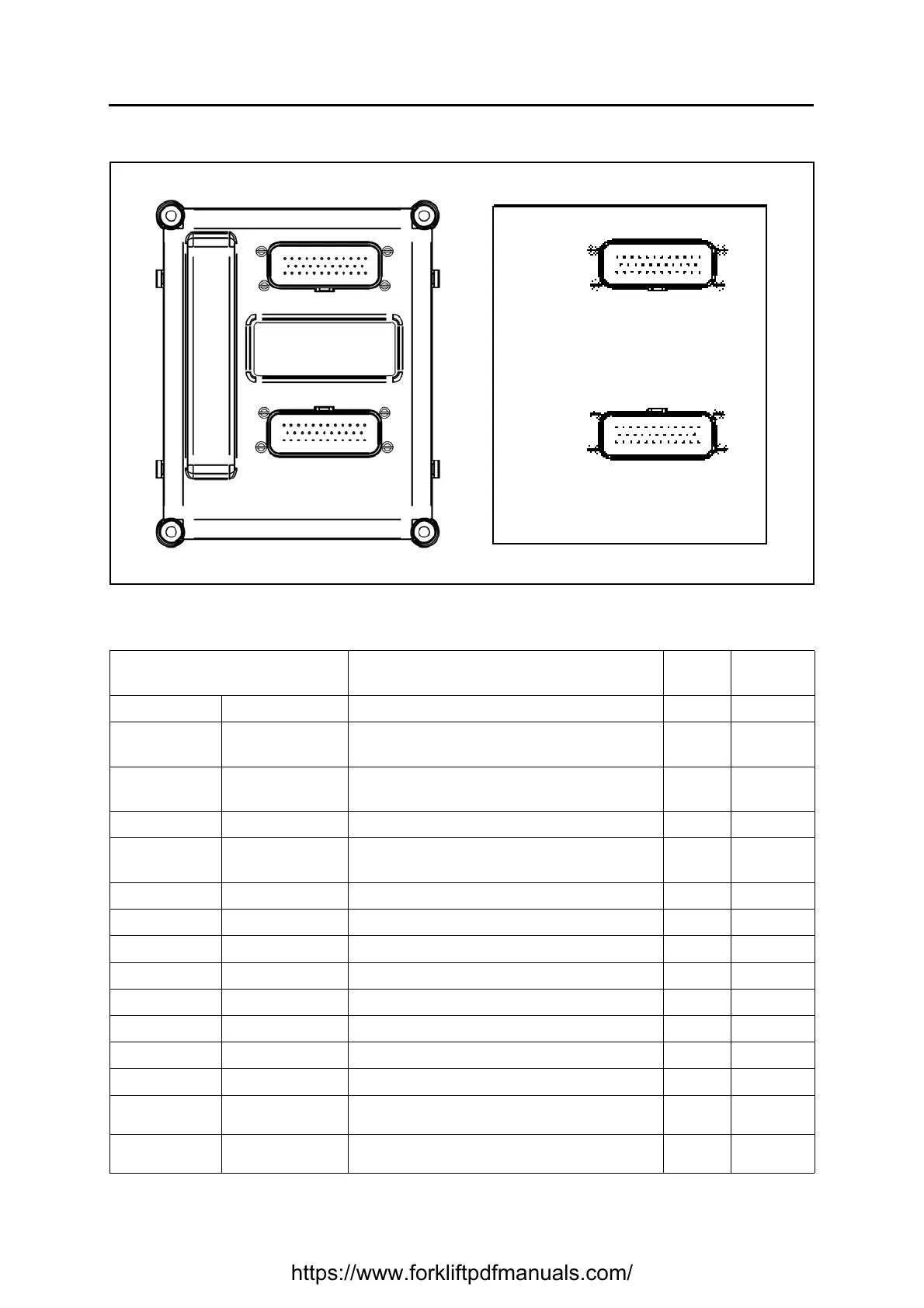
I/O BOARD
Basic conditions (battery plug connected, key switch ON).
See the reference names of the connectors in the electrical diagram.
CN (pin-colour) ⇔ CN (pin-colour)
From ⇔ To
Description Standard Notes
J34 (1-MN) J93 (2-MN) Output +V rear lights +Vb
J34 (2-HN)
J29 (2-HG)
J32 (2-HG)
Accelerator potentiometer negative ouptut GND
J34 (3-V)
J29 (1-V)
J32 (3-V)
Accelerator potentiometer cursor input 0 - 5V
J34 (4) --- Unused
J34 (5-AG)
J29 (3-AG)
J32 (1-AG)
Output + V accelerator potentiometer 5V
J34 (6-L) --- Negative input GND
J34 (7-N) --- Negative input GND
J34 (8-N) --- Negative input GND
J34 (9-B) J11 (2-B) Horn signal output GND
J34 (10-N) --- Negative input GND
J34 (11-R04) J50 (4-R02) Board power input +Vb
J34 (12-CR) J131 (4-CR) Armrest board power output +Vb
J34 (13-AM) J91 (2-AM) Output +V stop lights +Vb
J34 (14-NZ) J50 (10-NZ) Parking brake signal input 5V
GND with
micro closed
J34 (15-BZ) J31 (2-BZ) Brake pedal system signal input 5V
GND with
micro closed
(black connector)
(white connector)
J34
J40
https://www.forkliftpdfmanuals.com/
 Loading...
