2-16
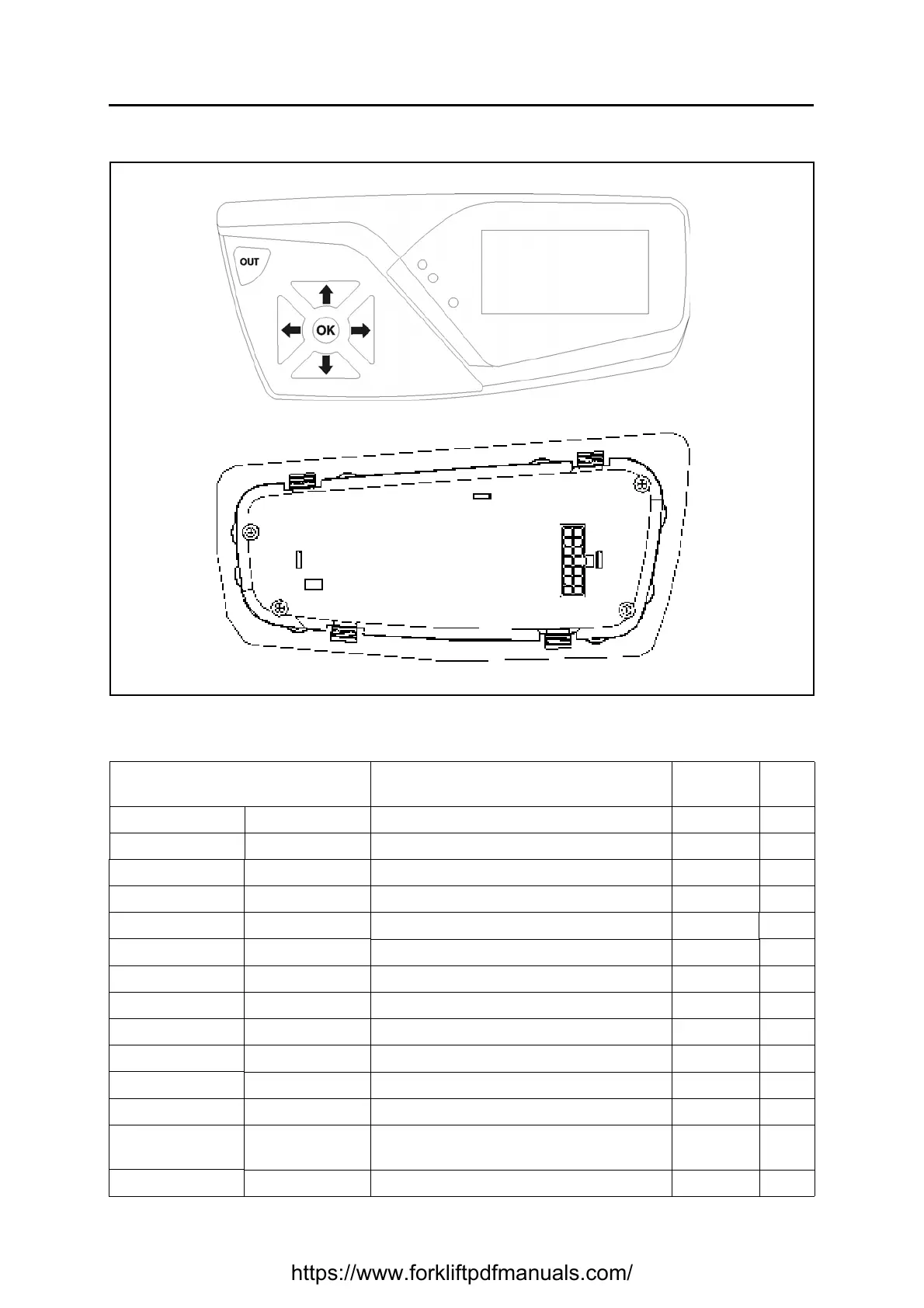
DASHBOARD
Basic conditions (battery plug connected, key switch ON).
See the reference names of the connectors in the electrical diagram.
CN (pin-colour) ⇔ CN (pin-colour)
From ⇔ To
Description Standard Notes
J137 (1-AN) CN1 (20-AN) CAN-BUS HIGH
J137 (2-HG) CN1 (22-HG) CAN-BUS LOW
J137 (3-N) J1 (-) Battery negative input GND
J137 (4-CL) J35 (5-CL) Turtle button signal input
J137 (5-RG) J35 (6-RG) LPH button signal input
J137 (6-RA) J4 (1-RA) Brakes oil level signal input
J132 (7-R04) J9 (2-R04) Key power input +Vb
J137 (8-AN) J132 (3-AN) CAN-BUS HIGH
J137 (9-HG) J132 (4-HG) CAN-BUS LOW
J137 (10) --- Unused
J137 (11) --- Unused
J137 (12) --- Unused
J137 (13-AB)
J71 (2-AB)
J50 (9-AB)
Alarm buzzer negative GND
J137 (14-N) --- Negative GND
https://www.forkliftpdfmanuals.com/
 Loading...
