9-3
Cisco SCE8000 Installation and Configuration Guide, Rel 3.1.7
OL-16478-03
Chapter 9 Removal and Replacement Procedures
Supported Hardware
Supported Hardware
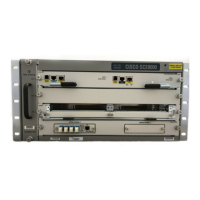
The Cisco SCE8000 platform supports the following hardware:
• One Service Control Module (SCE8000-SCM-E), with an optional redundant Service Control
Module (FRU).
• One SPA jacket module (SCE8000-SIP), with either two or four SPA 10GBE interface modules (all
FRU).
• Up to two optical bypass modules installed in the bottom slot of the chassis.
• Hot-swappable fan assembly, redundant AC-input or DC-input power supplies.
Removing and Replacing the Power Supply
This section describes how to remove and install power supplies for the Cisco SCE8000.
Note In systems with redundant power supplies, you can replace the faulty supply while the system is
operating.
• Required Tools, page 9-3
• Removing an AC-Input Power Supply, page 9-3
• Installing an AC-Input Power Supply, page 9-5
• Removing a DC-Input Power Supply, page 9-5
• Installing a DC-Input Power Supply, page 9-7
Required Tools
A flat-blade or number 2 Phillips-head screwdriver is required to perform these procedures.
Additionally, a wire cutter or scissors may be necessary for cutting cable tie-wraps.
Removing an AC-Input Power Supply
Warning
Hazardous voltage or energy is present on the backplane when the system is operating. Use caution
when servicing.
Step 1 Turn the power switch to the Off (0) position on the power supply you are removing.
Step 2 Disconnect the power cord from the power source. Do not touch the metal prongs on the power cord
when it is still connected to the power supply.
Step 3 Remove the power cord from the power connection on the power supply module. Do not touch the metal
prongs embedded in the power supply.
Step 4 Loosen the captive installation screws on the power supply.

 Loading...


