9-13
Cisco SCE8000 Installation and Configuration Guide, Rel 3.1.7
OL-16478-03
Chapter 9 Removal and Replacement Procedures
Removing and Replacing Modules
Removing and Replacing Modules
The Cisco SCE8000 platform supports two types of modules:
• Service Control Module (SCE8000-SCM-E)
• SPA Interface Processor (SCE8000-SIP)
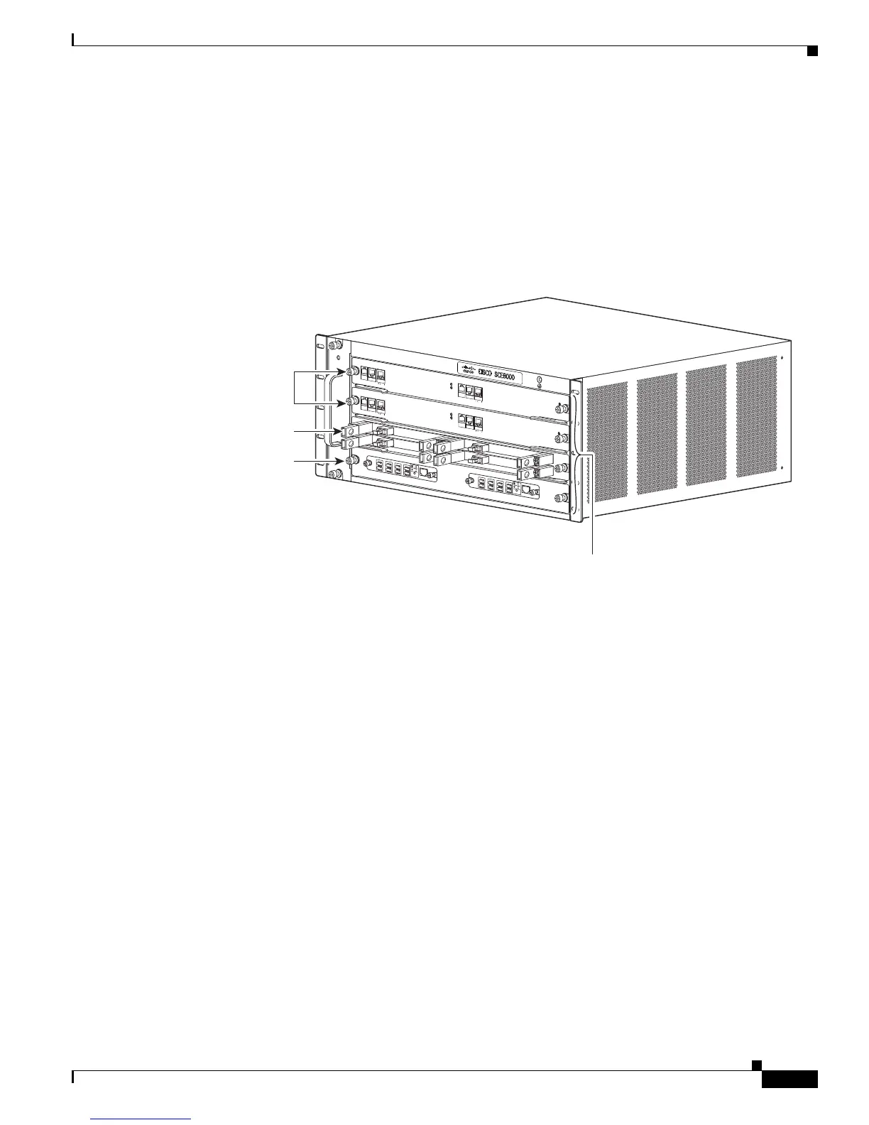
The following diagram shows the position of these modules in the Cisco SCE8000 chassis.
Figure 9-8 Slot Numbers on Cisco SCE8000 Chassis
Required Tools
These tools are required to remove or install modules in the Cisco SCE8000 chassis:
• 3/16-inch flat-blade screwdriver
• Number 2 Phillips screwdriver
• Wrist strap or other grounding device
• Antistatic container that the module was shipped in
Handling SIPs
Each SIP circuit board is mounted to a metal carrier and is sensitive to electrostatic discharge (ESD)
damage.
Always handle the SIP by the carrier edges and handle; never touch the SIP components or connector
pins. (See Figure 9-9.)
When a slot is not in use, a blank filler plate must be installed in the empty slot to allow the SCE platform
to conform to electromagnetic interference (EMI) emissions requirements and to allow proper airflow
across the installed modules. If you plan to install a SIP in a slot that is not in use, you must first remove
the blank filler plate.
FA
N STA
TUS
S
C
M
1
S
C
M
2
S
I
P
3
4
SCE8
00
0-F
A
N
S
Y
ST
E
M
P
OW
E
R
O
PTICAL
B
YPASS
S
T
A
T
U
S
A
U
X
PO
R
T2
L
I
N
K
AC
TI
VE
MA
STER
S
C
E8000
EX
T
E
N
DE
D
S
E
R
V
I
CE
C
O
NT
R
O
L
M
O
D
U
LE
O
PTI
C
A
L
B
Y
P
A
S
S
O
PT
I
C
A
L
B
Y
P
A
S
S
C
ON
SO
LE
1
0
1
0
0
1
0
0
0
LI
N
K
AC
T
I
V
E
P
O
R
T
1
A
C
A
B
C
D
B
D
S
TAT
U
S
C
T
R
L
O
P
B
-
S
C
E
8
K
-
M
M
O
P
T
I
CA
L
B
Y
P
A
S
S
1
T
X
R
X
T
X
R
X
T
X
R
X
T
X
R
X
A
C
A
B
C
D
B
D
S
TA
T
U
S
C
T
R
L
O
PB
-
S
CE8
K
-
M
M
OPT
IC
AL
B
YPASS2
T
X
R
X
T
X
R
X
T
X
R
X
T
X
R
X
S
Y
S
TEM
P
OWE
R
O
PTICAL
B
YPASS
ST
A
T
U
S
AUX
P
ORT
2
10
100
1000
L
I
N
K
A
C
T
I
VE
M
A
STER
S
C
E8000 EX
T
E
N
DE
D
S
E
R
V
I
C
E
C
O
NT
RO
L
M
O
DULE
S
C
E
8
0
0
0
-S
CM-E
S
C
E
8
0
0
0-S
CM-E
S
CE
8
0
0
0
-
S
IP
C
ON
SO
L
E
1
0
1
0
0
1
0
0
0
LI
N
K
AC
T
I
V
E
PO
R
T
1
O
P
T
I
C
A
L
B
Y
P
A
S
S
OPT
I
C
AL
B
Y
P
ASS
S
T
ATUS
A
C
T
I
V
E
/
L
I
N
K
S
P
A
-
1
X
1
0
GE-
L-
V
2
S
T
A
TU
S
A
C
T
I
V
E
/
L
I
N
K
S
P
A
-
1
X
1
0
G
E-
L-
V
2
S
T
A
T
U
S
A
C
T
I
V
E
/
L
I
N
K
S
P
A
-1
X
10
G
E
-
L
-
V2
S
T
A
T
U
S
A
C
T
I
V
E
/
L
I
N
K
S
P
A
-1
X
10
GE
-
L
-
V2
10
1
00
1000
270889
Slots 1-4
(top to bottom)
SCE8000-
SCMs
SCE8000-
SIP
Optional
Optical Bypass
Modules

 Loading...


