9-7
Cisco SCE8000 Installation and Configuration Guide, Rel 3.1.7
OL-16478-03
Chapter 9 Removal and Replacement Procedures
Removing and Replacing the Power Supply
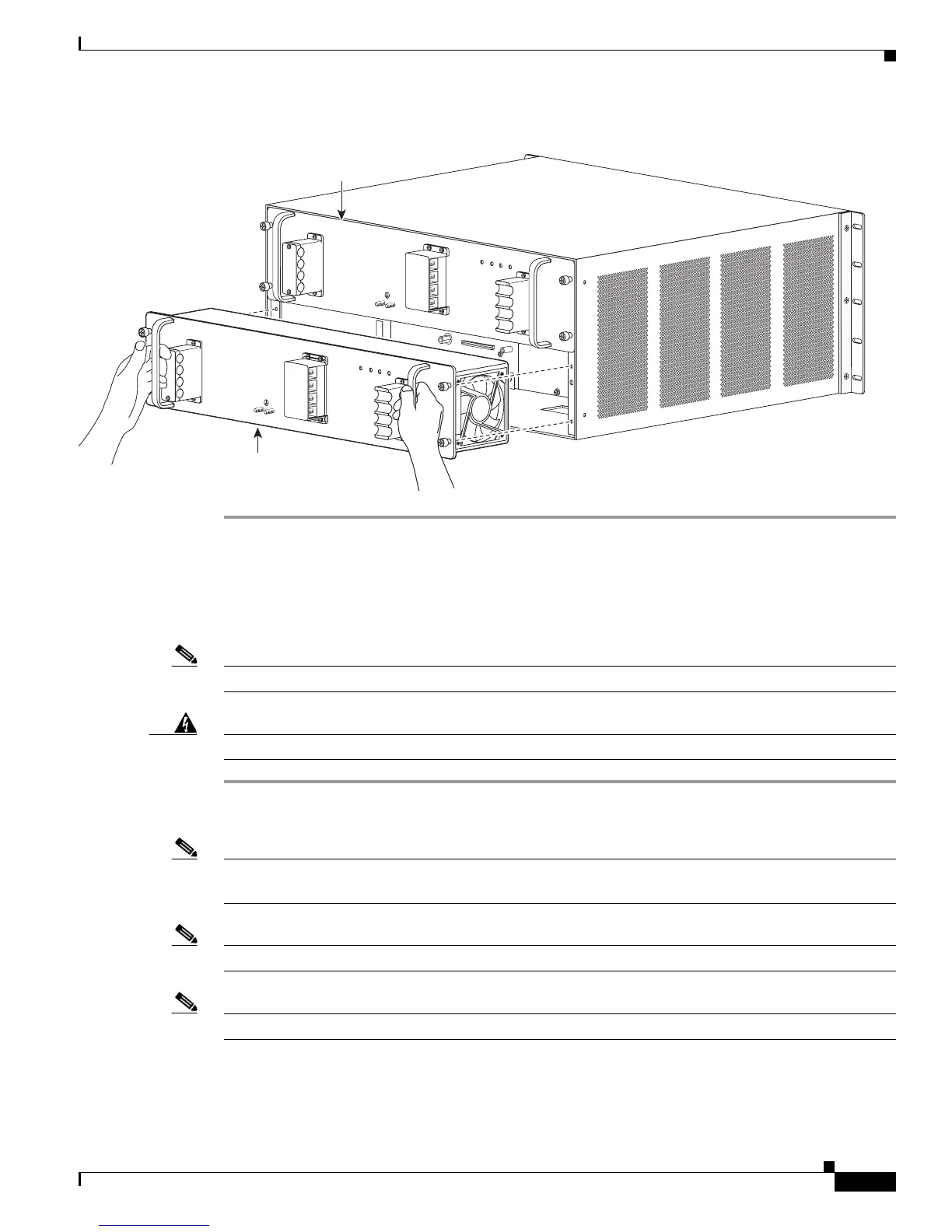
Figure 9-4 Handling a DC-Input Power Supply
Installing a DC-Input Power Supply
This section covers the DC-input power supply installation procedure for the Cisco SCE8000 chassis.
Note The DC return is to remain isolated from the system frame and chassis (DC-I).
Warning
Before performing any of the following procedures, ensure that power is removed from the DC circuit.
Step 1 Power supply ground is required. Install the PWR-2700-DC/4 power supply ground as described in this
procedure.
Note The system ground connection with the PWR-2700-DC/4 power supply in a Cisco SCE8000 is provided
by the PWR-2700-DC/4 power supply ground. Additionally, you can connect a system (earth) ground.
Note You must always connect the PWR-2700-DC/4 power supply ground.
Note You must connect the PWR-2700-DC/4 power supply ground for both power supplies.
126567
PWR-2700-DC/4
ALL FASTENERS MUST BE FULLY ENGAGED
PRIOR TO OPERATING THE POWER SUPPLY
INPUT1
OK
48V-60V
=40A
INPUT2
OK
48V-60V
=40A
FAN
OK
OUTPUT
FAIL
+VE-1
-VE-1
+VE-2
-VE-2
ALL FASTENERS MUST BE FULLY ENGAGED
PRIOR TO OPERATING THE POWER SUPPLY
INPUT1
OK
48V-60V
=40A
INPUT2
OK
48V-60V
=40A
FAN
OK
OUTPUT
FAIL
PWR-2700-DC/4
+VE-1
-VE-1
+VE-2
-VE-2
+VE-1
-VE-1
+VE-2
-VE-2
+VE-1
-VE-1
+VE-2
-VE-2
Power Supply 2
(redundant)
Power Supply 1

 Loading...


