ELECTRICAL SYSTEM
97
2. To re-arm and turn the module ON:
If the key is in REVERSE CAUTION MODE
position, it must be turned to another position
(Normal Run), then returned to REVERSE CAU-
TION MODE. Once re-armed, the module can
be turned-on by pressing orange triangular but-
ton. It will be confirmed that the module is ON by
the illumination of the red LED on the module.
3. To identify a faulty RMC module: If the RMC
module does not function as described, the RMC
plug test should be the first step in diagnosis.
• If the RMC plug test confirms that the safety cir-
cuits (inputs) work as designed, yet the RMC
module does not work properly, the RMC mod-
ule is faulty.
• The RMC plug test will give an indication of what
the problem is if it is not a faulty RMC module. If
the problem is identified in a particular circuit,
check the safety switch that is associated with
that circuit. If the switch is good, then the prob-
lem lies within the wiring harness.
NOTE: Like the electronic components found on
most cars, the RMC module requires a fully
charged battery to work properly. If the system
voltage falls below 12 V. an accurate diagnosis
of the RMC module is impossible because the
module will be temporarily disabled by low volt-
age.
RMC module plug test (electric PTO)
1. Disconnect the molded 8-pin plug from the RMC
module. See Figure 7.5.
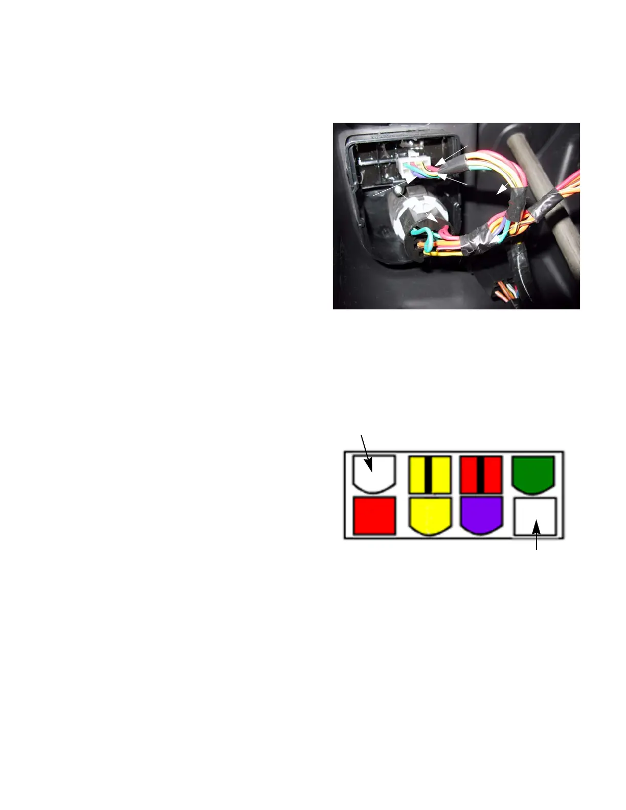
2. Looking at the plug head-on, it will be configured
as shown in the diagram: There will be 8 female
pin terminals. When probed they should yield the
results described in the following sections.
See Figure 7.6.
Figure 7.5
Purple
Red
Yellow/Black
Figure 7.6
Empty
Empty
 Loading...


