ELECTRICAL SYSTEM
99
• Interpretation: If the purple wire fails to reach a
ground path when the key switch is in the
REVERSE CAUTION MODE position, the RMC
module will not arm or operate. Check the key
switch for continuity between A2 and L in the
REVERSE CAUTION MODE position, confirm
that the green wire connecting to the L terminal
does have good continuity to ground, and check
for any loss of continuity in the purple wire that
extends from the key switch to the RMC module,
including the molded connector between the two
components.
9. If the RMC plug test indicates fault with any of
the safety switches, the next step is to test the
suspect switch. The operation of those switches
is described in the following sections.
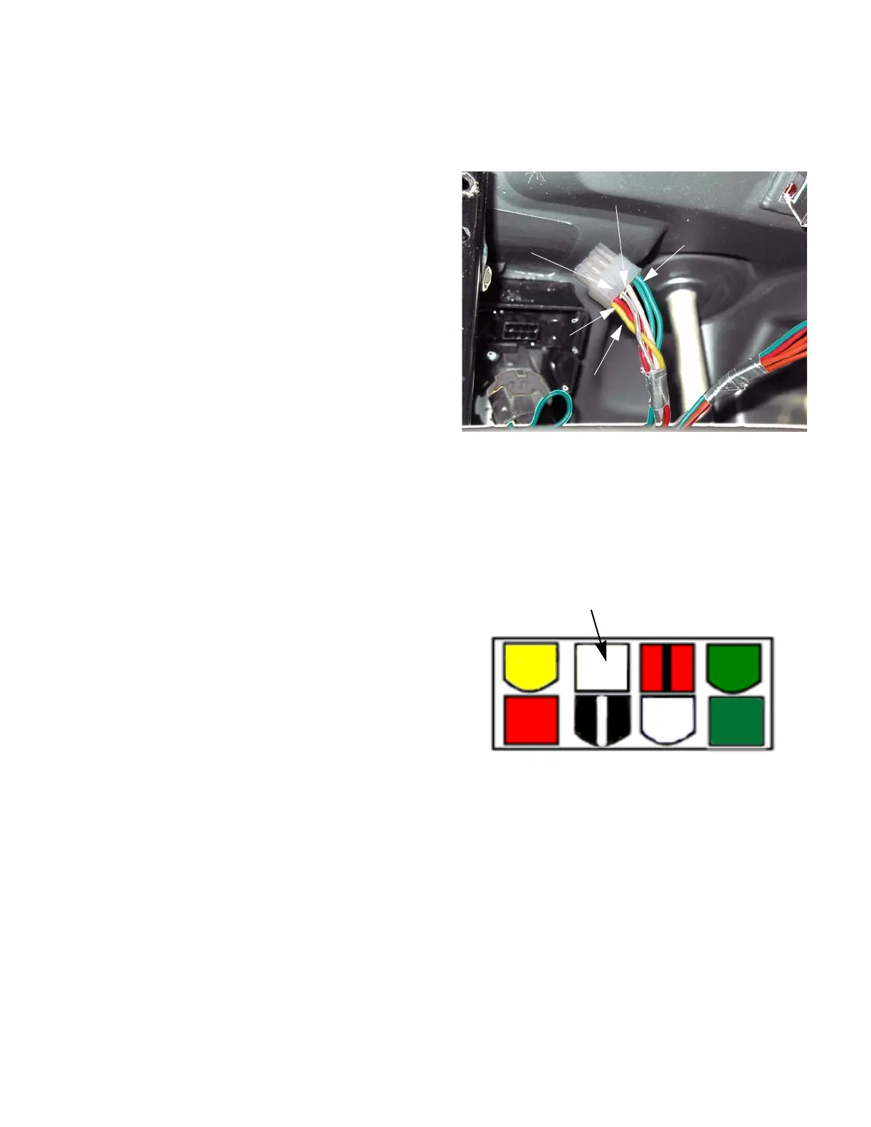
RMC module plug test (manual PTO)
1. Disconnect the molded 8-pin plug from the RMC
module. See Figure 7.7.
2. Looking at the plug head-on, it will be configured
as shown in the diagram: There will be 8 female
pin terminals. When probed they should yield the
results described in the following sections.
See Figure 7.8.
Figure 7.7
white
Red
Green
Black/white
Yellow
Figure 7.8
Empty
 Loading...


