CVT Drive and brake system
69
4. Slip the tie plate off of the hex bushing, and
remove it.
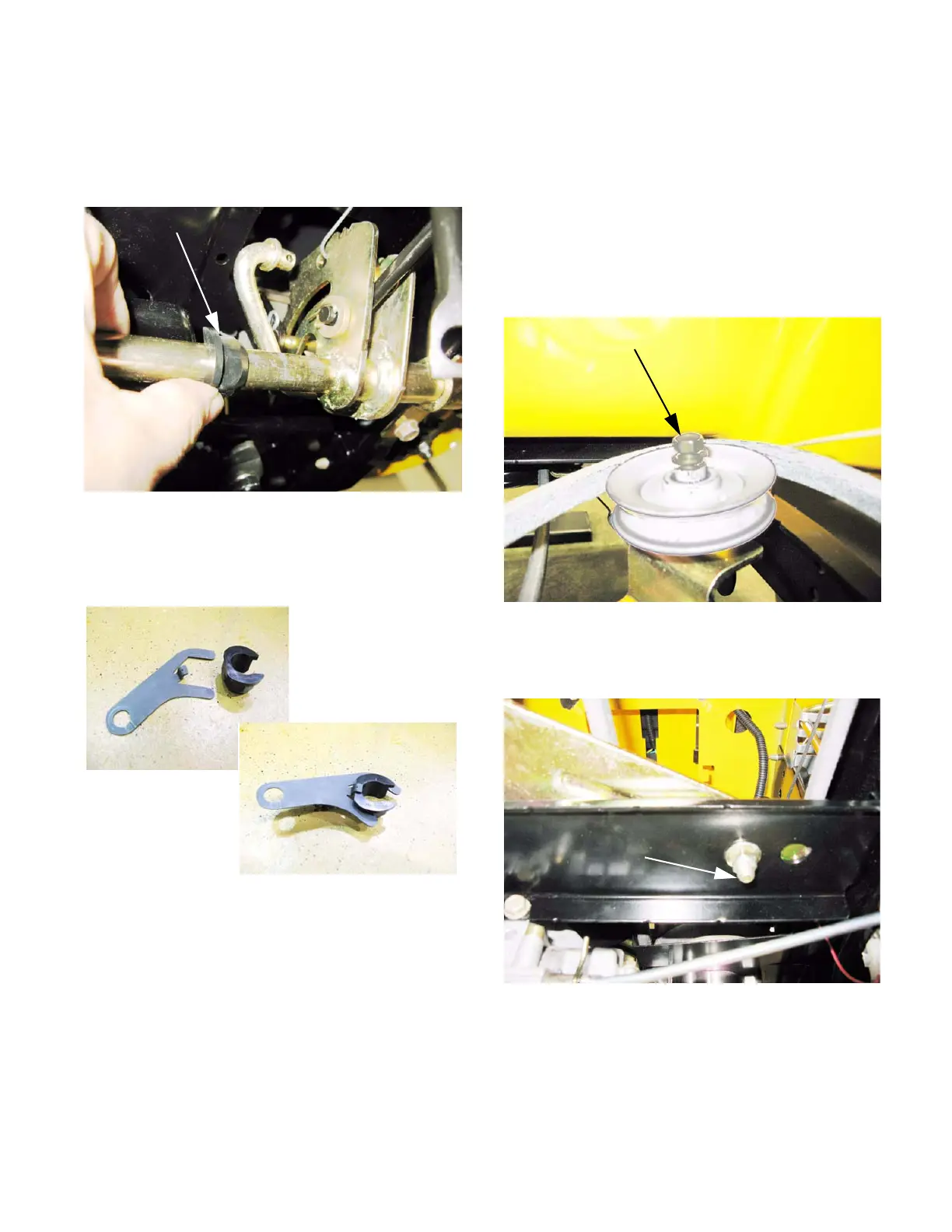
5. Snap the hex bushing off of the brake pedal
shaft. See Figure 6.35.
NOTE: The hook on the tie strap goes over the
trimmed section of the flange on the hex bush-
ing. See Figure 6.36.
6. Install the tie strap by reversing the process
used to remove it. Use a new cotter pin.
7. Test-drive the tractor to confirm that the drive
system is working correctly before returning it to
service.
Figure 6.35
Hex bushing
Figure 6.36
Belt control: tension make-up pulley
CAUTION: The battery will be removed in this
procedure. Review the Operator’s Manual and
Chapter 7: Electrical Systems for important
safety information about handling batteries
before proceeding.
1. Remove the upper drive belt from the make-up
tensioner pulley as described in the drive belts
section of this chapter. See Figure 6.37.
2. Unbolt the arm from the torque bracket using a
pair of 9/16” wrenches. See Figure 6.38.
Figure 6.37
Bolt loosened
Figure 6.38
Tension make-up
arm pivot bolt
 Loading...


