CVT Drive and brake system
70
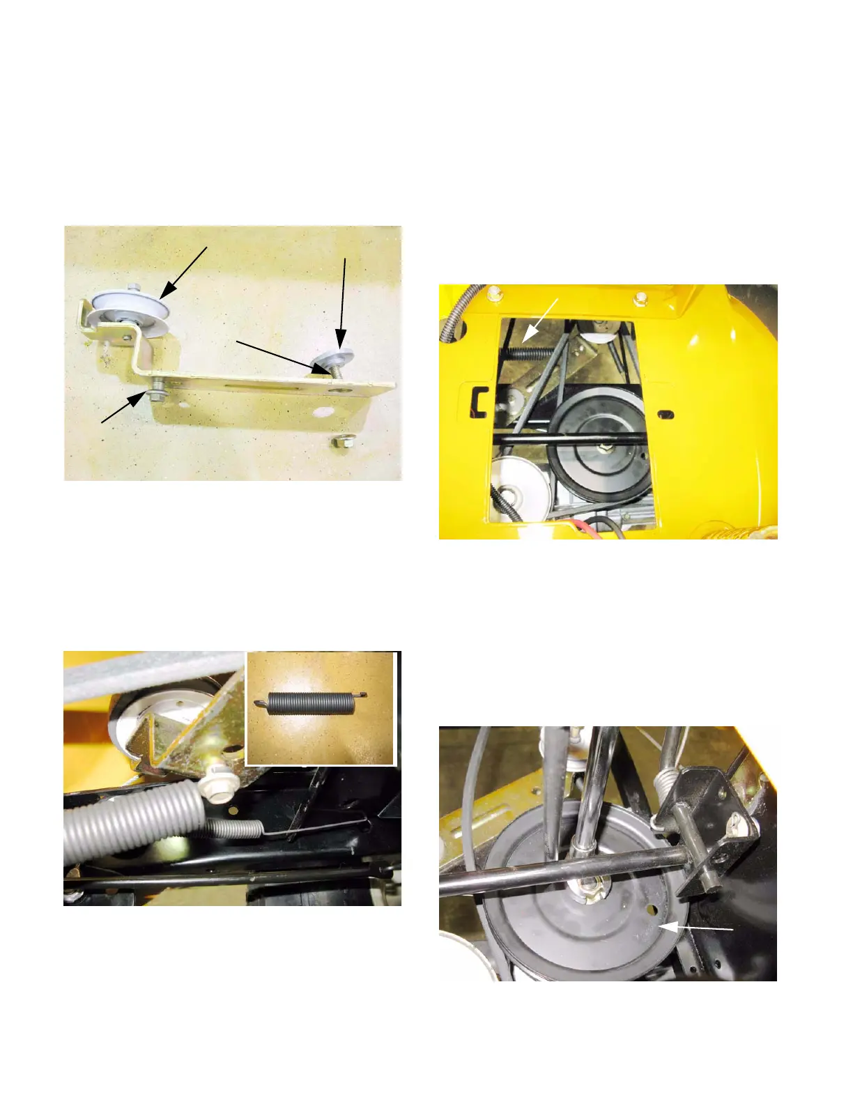
3. The arm pivots on a shouldered bushing.
See Figure 6.39.
• A shoulder bolt threads into the bottom of the
arm, for the tension spring to hook onto.
• The tension make-up pulley bolts to the top of
the arm.
4. Install the arm by reversing the procedure used
to remove it.
• Lubricate the pivot point with grease or anti-
seize compound.
• One end of the tensioner spring is off-set. The
off-set end connects to the arm.
Belt control: variable speed pulley
CAUTION: The battery will be removed in this
procedure. Review the Operator’s Manual and
Chapter 7: Electrical Systems for important
safety information about handling batteries
before proceeding.
1. Remove the battery and battery tray by following
the procedures described in Chapter 4: Body
Panels. See Figure 6.41.
2. Disconnect the lateral spring from the frame,
relieving tension from the make-up pulley.
3. Roll the upper drive belt off of the transmission in
put pulley and the top sheave of the variable
speed pulley.
4. Remove the input pulley from the transaxle
using a 7/8” wrench. See Figure 6.42.
Figure 6.39
Tension make-up pulley Shoulder bushing
Mounting bolt
Shoulder bolt
Figure 6.40
Figure 6.41
Lateral spring
Figure 6.42
Input
pulley
 Loading...


