ELECTRICAL SYSTEM
124
Voltage Drop Test
To review:
• Ohm’s law states that it takes voltage to push
current through a resistance.
• Kirchhoff’s voltage law states that the sum of all
the voltage drops equals the source voltage.
• Combining those two laws, we see that any
restriction in a circuit (e.g.: loose connector dam-
aged wire, or corroded terminal) will use up
some voltage as the current is pushed through.
• A voltage drop test is a way of looking for that
voltage.
• Because electricity needs to complete a full cir-
cle (circuit), voltage drop tests are useful on both
the positive or the negative side of the system.
• This text will address the negative side to begin
with. Bad grounds are responsible for as many
electrical failures as the positive side of the sys-
tem, yet the ground side is frequently neglected
by technicians. See Figure 7.47.
IMPORTANT: Ultimately, all current will find its
way back to the negative post of the battery.
To check ground-side voltage drop: set-up a multimeter
to measure 12V DC.
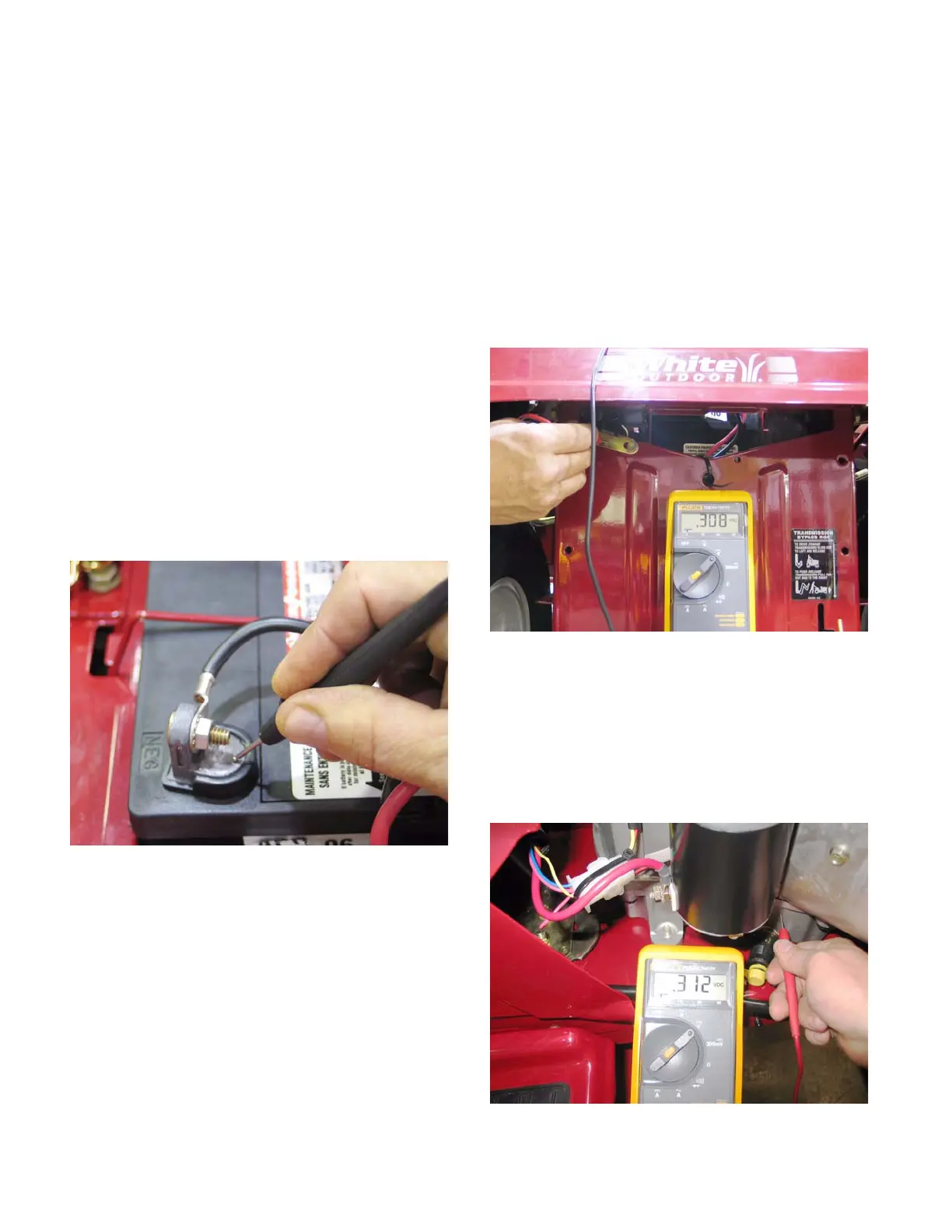
1. Make a good electrical connection between the
black (-) probe and the negative post on the bat-
tery.
2. Make a good electrical connection between the
red (+) probe and the suspect point of ground.
3. Power-up the circuit in question.
4. The voltage that shows-up on the meter is the
voltage that is being used to pass current
through a resistance in the circuit.
5. Voltage drop on a good circuit should be less
than 0.1 volts. A voltage drop reading on the
meter of greater than 0.2 volts indicates a fairly
substantial problem that demands attention.
• As an example, if the starter solenoid does not
engage properly, check for voltage drop between
the ground point for the starter solenoid and the
negative post on the battery. See Figure 7.48.
NOTE: With the starter engaged, this machine
exhibited a voltage-drop reading of 0.308 volts,
indicating a poor ground connection.
6. A similar ground-side test on a tractor with a
slow-cranking starter motor can be conducted
between the engine block and the negative bat-
tery post. See Figure 7.49.
Figure 7.47
Figure 7.48
Figure 7.49
 Loading...


