HYDRO. DRIVE AND BRAKE SYSTEM
41
NOTE: Leaving the drive control pedal shaft
loose until after the brake rod is secured will
make it easier.
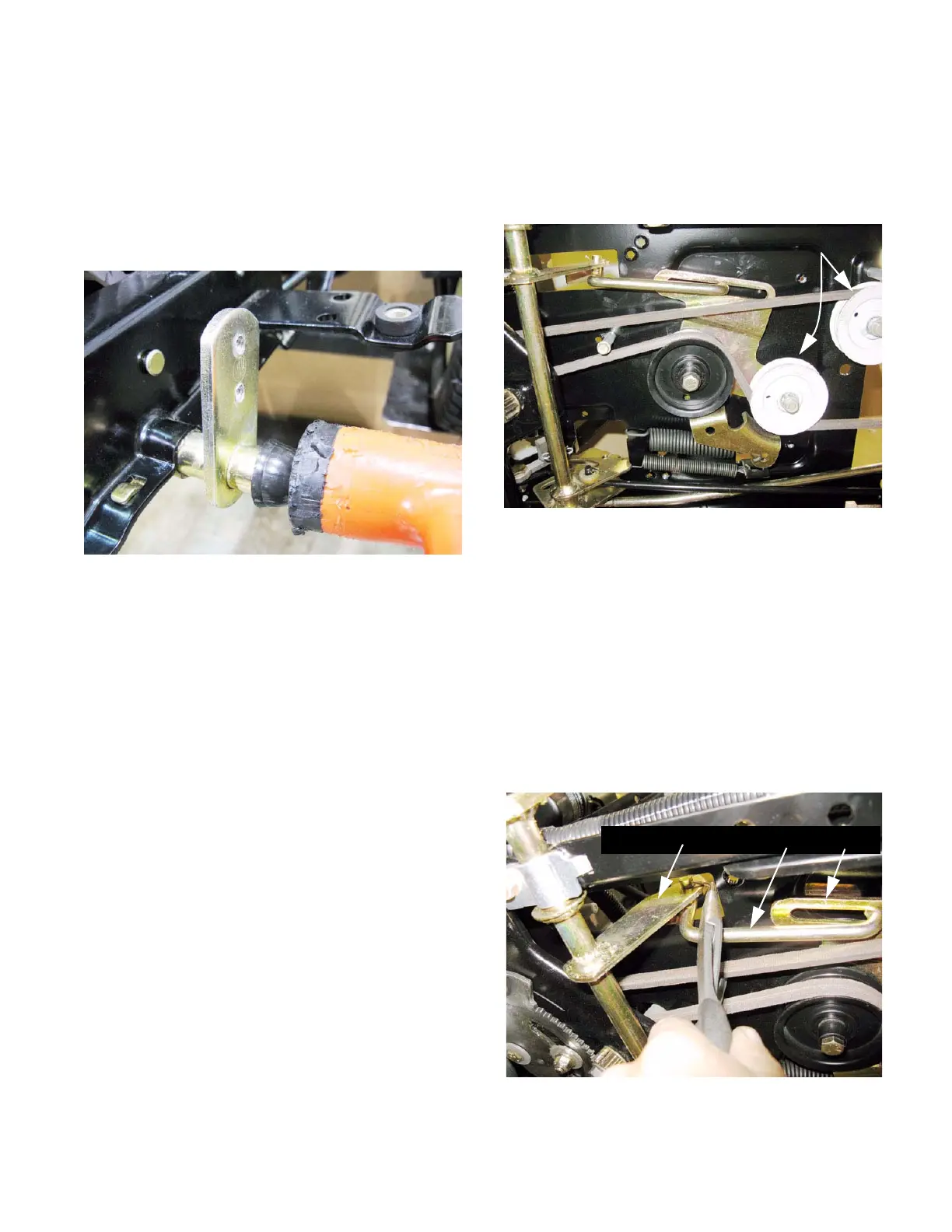
15b. Position the drive control shaft and bush-
ings, fasten the drive control rod to it, then
drive the push cap on. See Figure 5.34.
15c. Tighten the pedal shaft support strap bolts
to a torque of 12-15 ft-lbs. (16-20 N-m).
15d. Attach the belt tensioner pulley rod.
16. Test the drive system and all safety features
before returning the tractor to service.
Figure 5.34
Belt control; tensioner and idler pulleys
NOTE: The V-idler pulleys can be removed from
below using a 1/2” wrench, with no disassembly
beyond removing the cutting deck.
See Figure 5.35.
NOTE: Confirm that the parking brake is
released before starting work.
1. Remove the mowing deck.
2. Remove the fenders by following the steps
described in Chapter 4: Body Panels.
3. Disconnect the rod that joins the arm at the left
side of the clutch/brake shaft to the drive belt
tensioner pulley bracket. See Figure 5.36.
• Remove and discard the cotter pin to disconnect
the rod.
Figure 5.35
V-sheave
pulleys
Figure 5.36
Clutch/brake shaft Rod Bracket
 Loading...


