HYDRO. DRIVE AND BRAKE SYSTEM
42
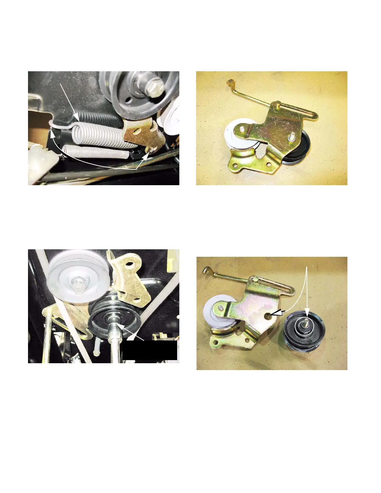
4. Disconnect the extension spring that pulls on the
bracket to tension the drive belt.
See Figure 5.37.
5. Note the belt routing, then slip the drive belt off
of the two pulleys on the tensioning bracket.
6. Remove the nut and bolt that hold the belt ten-
sioner pulley bracket to the frame using a pair of
9/16” wrenches. See Figure 5.38.
7. Maneuver the belt tensioner bracket assembly to
clear the belt, and remove it from the tractor.
See Figure 5.39.
NOTE: The bracket assembly pivots on the bolt
that passes through the fixed, flat-sheave idler
pulley.
8. On the bench, the flat-sheave idler pulley, and
the spacers used to position it can be lifted off of
the pulley bracket. See Figure 5.40.
Figure 5.37
Extension spring
Mounting points
Figure 5.38
Remove this bolt.
Nut is above frame
Figure 5.39
Figure 5.40
Bracket pivot point
 Loading...


