HYDRO. DRIVE AND BRAKE SYSTEM
43
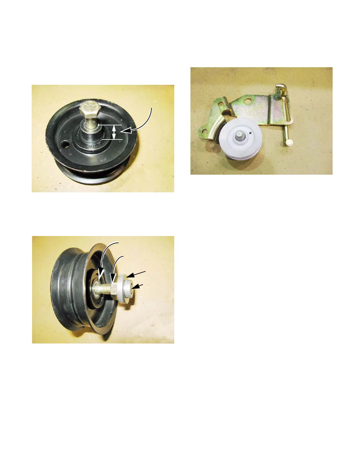
NOTE: When installed, the head of the bolt that
holds the bracket assembly to the tractor rests
against the shouldered side of the flat sheave
idler pulley. See Figure 5.41.
• When installed, the spacers fit against the flat
side of the flat sheave idler pulley.
See Figure 5.42.
9. The V-sheave tensioner pulley can be un-bolted
from the bracket using a 1/2” wrench.
Figure 5.41
Shoulder height
Figure 5.42
Flat surface
Hex bushing
Shoulder bushing
Bolt
Flat sheave pulley
10. The rod that connects the bracket to the clutch/
brake pedal shaft can be maneuvered to come
out of its slot in the bracket. See Figure 5.43.
11. Assemble and install the belt tensioner pulley by
reversing the steps used to remove and disas-
semble it.
• Lubricate the pivot point with a good quality lith-
ium-base grease.
12. Reinstall the fenders.
13. Test the drive system and all safety features
before returning the tractor to service.
Figure 5.43
 Loading...


