ELECTRICAL SYSTEM
103
Brake switch (manual PTO)
• The brake switch is mounted on the top side of
the frame, on the left side behind the dash.
• The brake switch used on manual PTO tractors
is a triple pole single throw switch. It has one set
of contacts that are normally closed (NC) and
the other two sets are normally open (NO).
See Figure 7.12.
• The plunger on the switch is depressed when
the clutch / brake pedal is pressed-down, de-
clutching the drive belt and applying the brakes.
The switch contains two sets of contacts.
• The normally closed (NC) set of contacts is in
the safety shut-down circuit. If the seat is vacant
the seat switch contacts will close connecting
the yellow wire with white trace
to ground. When
the brake pedal is up, the contacts close con-
necting the ground signal in the yellow wire with
white trace to the module through the yellow
wire.
• A normally open (NO) set of contacts is in the
starter inhibit circuit. When the clutch / brake
pedal is depressed, the contacts are closed,
power coming from the key switch (key switch in
START) through the orange wire
is passed on to
the PTO switch through the orange wire with
black trace.
• The other set of NO contacts receives the signal
from the parking brake switch through the pur-
ple wire. When the brake pedal is down, the con-
tacts close, sending that signal to the RMC
module through the black wire with white trace
.
0OLE"./
0OLE!.#
0OLE#./
Figure 7.12
To access the brake switch:
1. Remove the deck by following the steps
described in Chapter 8: Cutting Decks and Lift
Shaft.
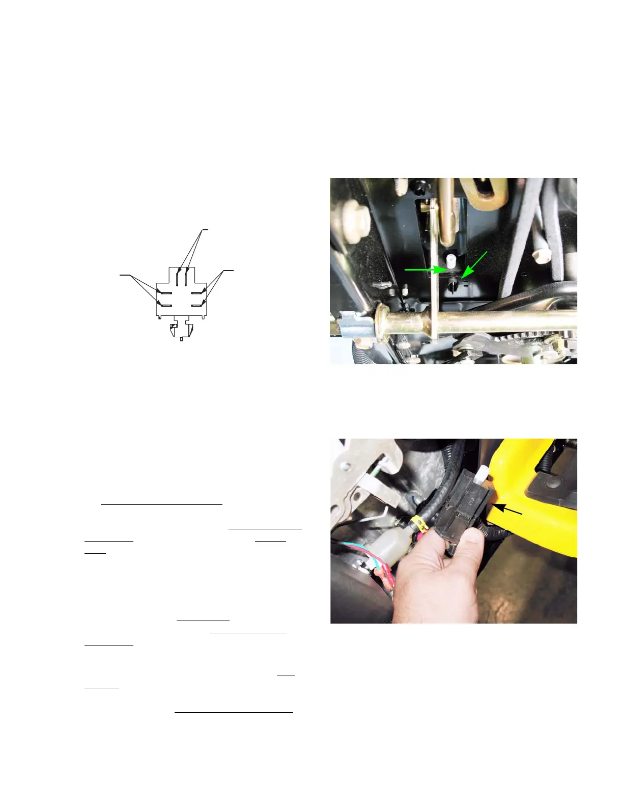
2. Squeeze the tab on the underside of the brake
switch with a pair of pliers, while pushing up on
the brake switch. See Figure 7.13.
3. Reach in between the left side of the engine and
the dash. Pull the switch and harness pigtail out
as one piece. See Figure 7.14.
4. Install the brake switch by following the previous
steps in reverse order.
Figure 7.13
Brake switch
Tab
Figure 7.14
Brake switch
 Loading...


