310-0510 IHT
12
RETURN TO NEUTRAL SETTING (FOOT CONTROL)
The return to neutral mechanism on the trans-
mission is designed to set the directional con-
trol into a neutral position when the operator
removes their foot from the foot control. Follow
the procedures below to properly adjust the
return to neutral mechanism on the transaxle:
1. Confirm the transaxle is in the operat-
ing mode (bypass disengaged). Raise the
vehicle’s drive tires off the ground to allow
free rotation.
NOTE: It may be necessary to remove
the drive tire from the axle hub to access
the linkage control and the transaxle
return arm.
2. Remove the Original Equipment Manufac-
turer’s (OEM’s) control linkage at the control
arm. Refer to Figure 5.
3. Start the engine and increase the throttle to
full engine speed.
4. Check for axle rotation. If the axles do not
rotate, go to Step 5. If the axles rotate, go to
Step 6.
5. Stop the vehicle’s engine. Reattach and ad-
just the OEM linkage according to the OEM
manual. Recheck according to Step 3 and
4. Stop the vehicle engine. Refer to Figure
5.
6. Note the axle directional movement. Stop
the vehicle engine. Loosen the adjusting
puck screw until the puck can be rotated.
Rotate the adjusting puck the opposite di-
rection of the wheel rotation in 5 degree in-
crements. Tighten the adjusting puck screw.
Refer to Table 5. Required Torque Values,
Page 15. Recheck according to steps 3 and
4. Stop the vehicle engine. Reattach and
adjust the OEM linkage according to the
OEM manual. Recheck according to steps
3 and 4. Refer to Figure 5.
WARNING
POTENTIAL FOR SERIOUS INJURY
Certain procedures require the vehicle
engine to be operated and the vehicle
to be raised off the ground. To prevent
possible injury to the servicing techni-
cian and/or bystanders, insure the
vehicle is properly secured.
WARNING
Do not attempt any adjustments with the
engine running. Use extreme caution while
inspecting all vehicle linkage!
Follow all safety procedures outlined in the
vehicle owner’s manual.
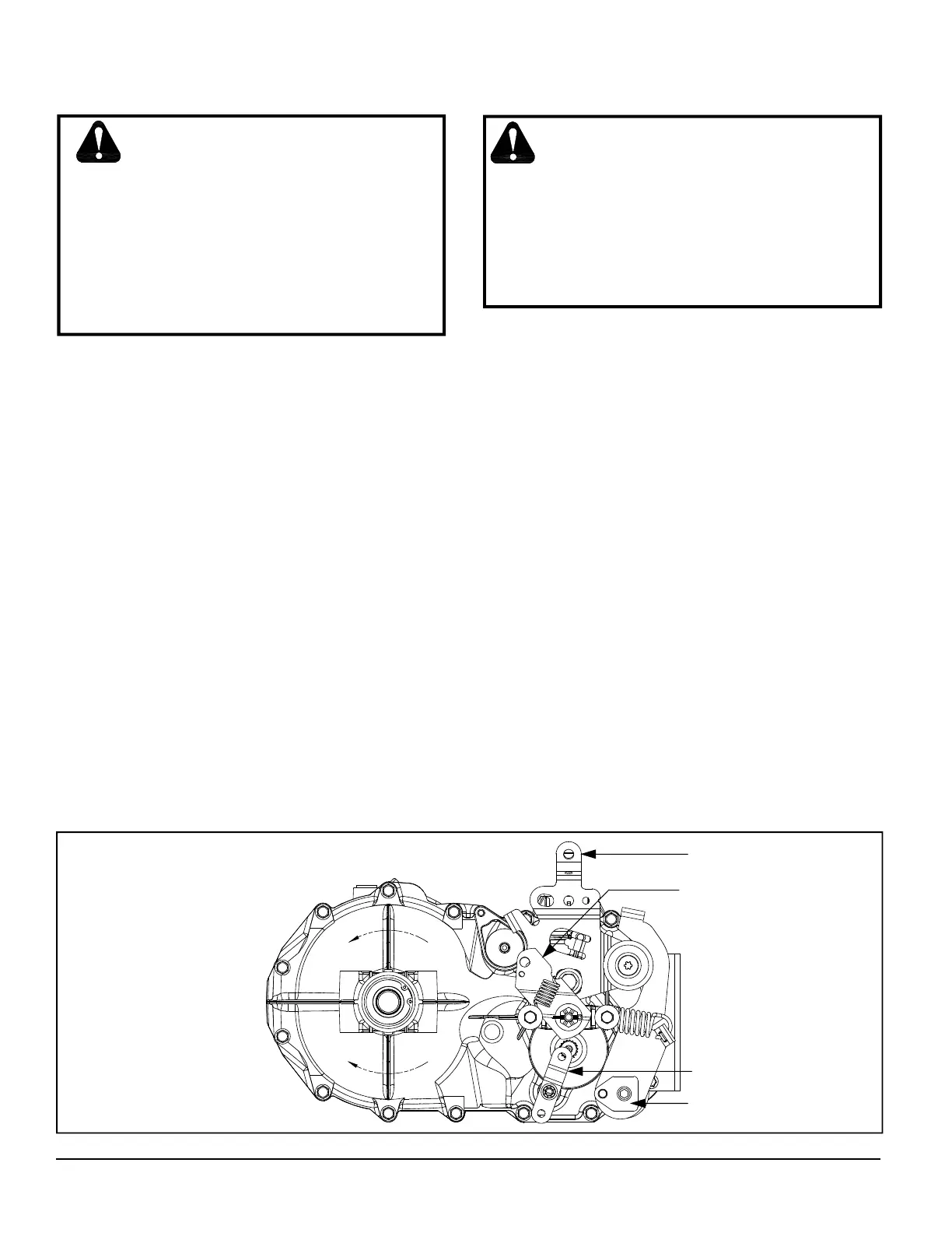
Figure 5. Return to Neutral, Foot Control
Control Arm
Bypass Arm
ROTATION B
ROTATION A
Brake Arm
Adjusting Puck
 Loading...


