ELECTRICAL SYSTEM
102
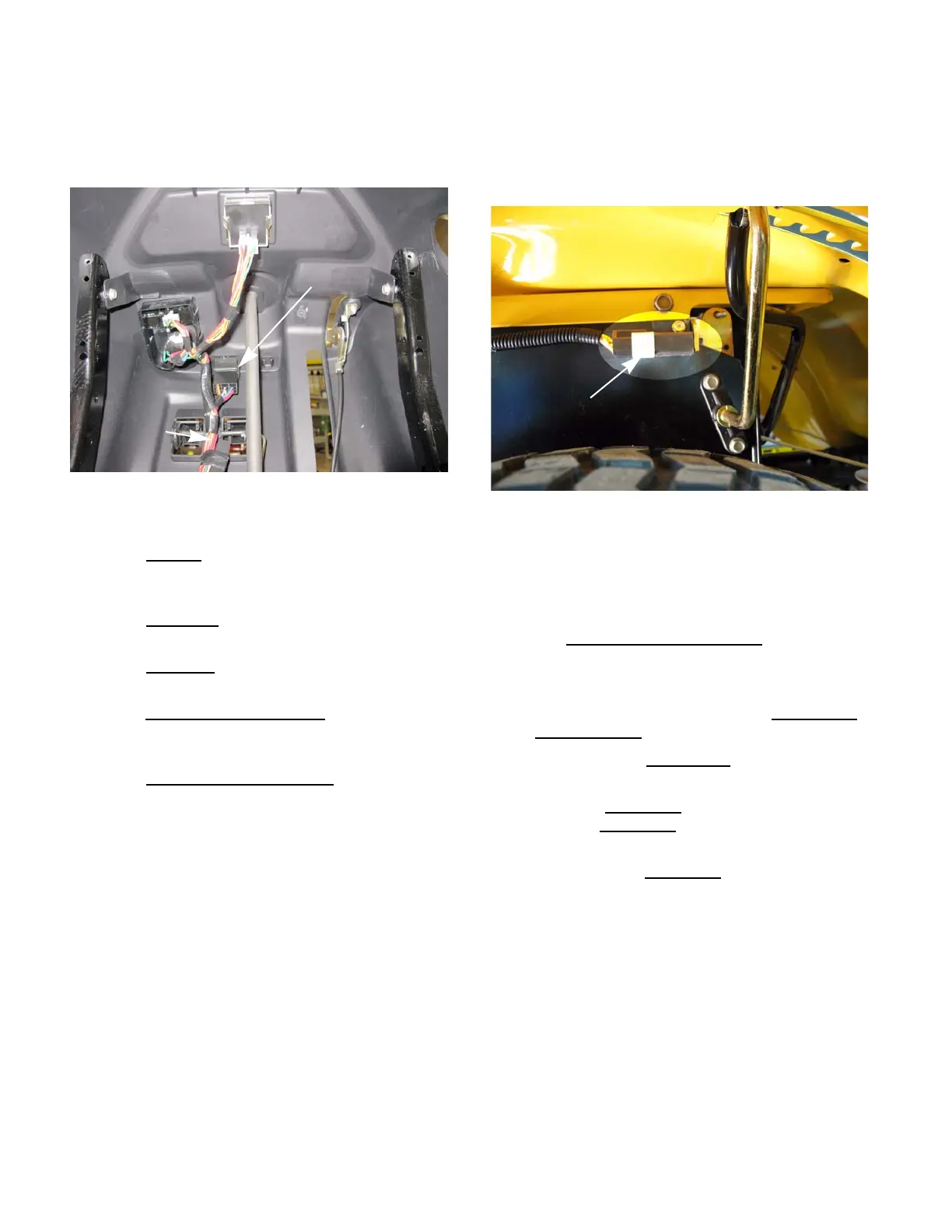
PTO relay
The PTO relay is located on the main harness, under-
neath the electric PTO switch. See Figure 7.10.
The PTO relay has 5 wire going to it:
• The red wire
is battery power from the A1 termi-
nal of the key switch. It is connected to the coil of
the relay.
• The green wire
is a ground wire. It is connected
to the common terminal of the relay.
• The white wire
connects the NC terminal of the
relay to the ground side of the PTO clutch.
• The white wire with black trace
connects the NO
terminal of the relay to the “B” circuit terminals of
the electric PTO switch.
• The yellow wire with black trace
connects the
coil of the relay to the “B” circuit terminals of the
electric PTO switch.
To access the PTO relay, remove the fuel tank by fol-
lowing the step described in Chapter 2: Engine Related
Parts.
NOTE: The PTO relay should be mounted so
that the terminals face down. This helps to keep
water out of the relay. The PTO relay connector
can be filled with petroleum jelly before inserting
the relay. This will also help to keep moisture out
of the relay.
NOTE: Electrical tape that is wrapped tightly
around the relay can prevent the relay from
operating properly.
PTO switch (manual PTO)
• The manual PTO switch is mounted on the right
side of the seat box section of the frame.
See Figure 7.11.
• The PTO switch plunger is depressed when the
PTO lever is moved to the “off” position.
• The switch has two pair of contacts: one NO and
one NC.
• The Orange wire with black trace
connects to
one of the NO terminals of the PTO switch.
When the PTO is turned “off” the NO contacts
close, completing a circuit from the brake switch
to the starter solenoid through the orange wire
with white trace.
• There are three yellow wires
connected to the
NC terminals.
1. The yellow wire
from the seat switch and
the yellow wire
from the RMC module are
connected to the same terminal.
2. The other yellow wire
goes to the ignition
module.
3. If the seat is empty or an unsafe condition
is sensed by the RMC module, a ground
signal is sent to the PTO switch. If the PTO
is “on” the ground signal will pass through
the switch and go to the ignition module
turning the engine off.
Figure 7.10
PTO relay
Electric PTO switch
Figure 7.11
Manual PTO switch
 Loading...


