ELECTRICAL SYSTEM
107
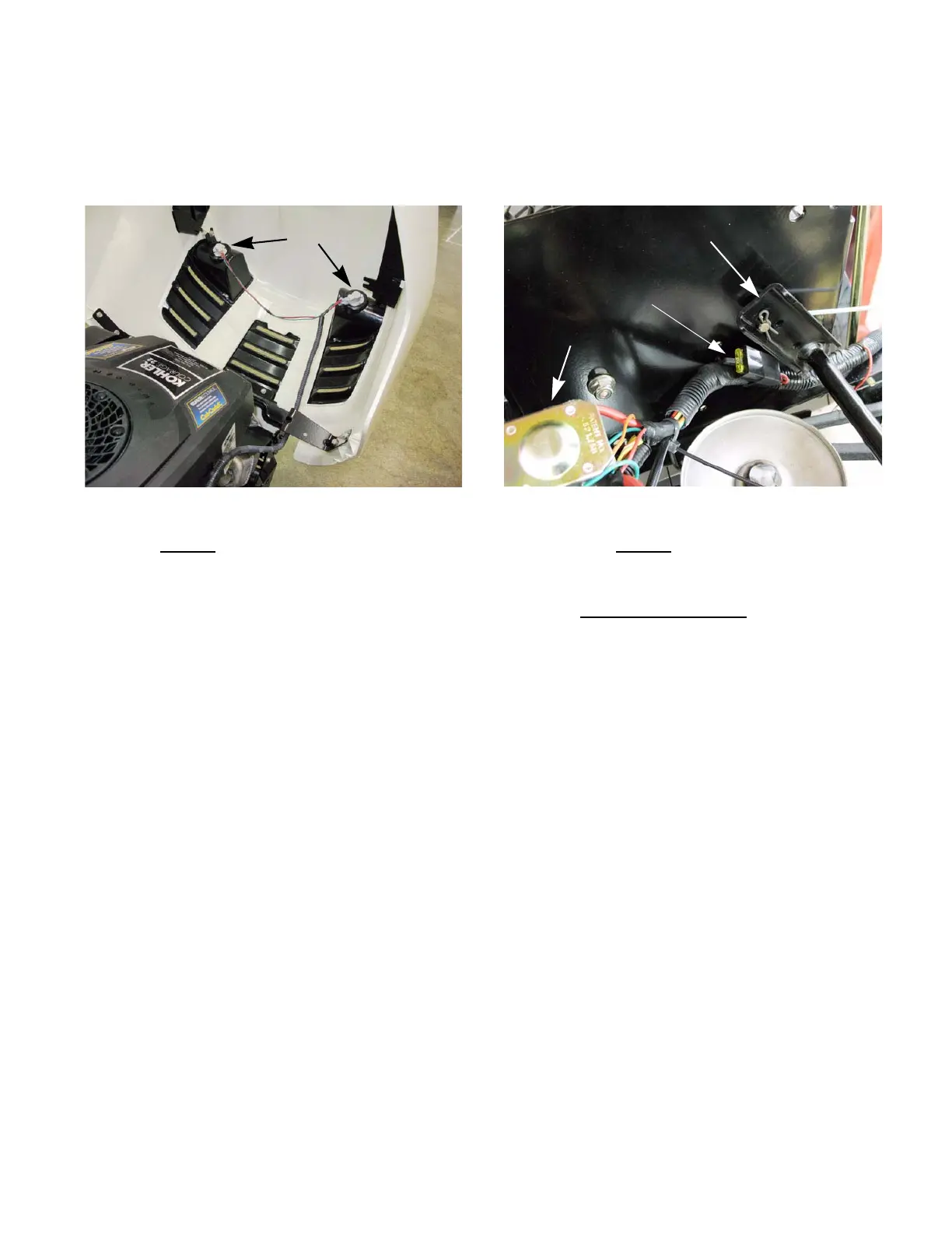
Lighting circuit
The lighting circuit is hot whenever the engine is run-
ning. It receives it’s power from the A1 terminal of the
key switch. See Figure 7.23.
• The red wire
carries battery power, the green
wire is a ground.
Figure 7.23
Headlights
Fuse
The 20A fuse is located inside the seat box section of
the frame, on the left side near the deck lift shaft.
See Figure 7.24.
• The solid red wire
feeds the fuse with power
picked-up from the battery cable connection to
the “hot” post of the starter solenoid.
• The red wire with white trace
carries fused
power to the B terminal on the key switch.
• A failed fuse will disable most of the tractor’s
electrical system.
• Remember that a failed fuse has done it’s job of
protecting the rest of the circuit from an over-
load. If a fuse blows, figure-out why and correct
the core problem before returning the tractor to
service.
Figure 7.24
20 Amp fuse
Deck lift shaft
Starter solenoid
 Loading...


