CVT Drive and brake system
65
Pedal shaft assembly removal:
NOTE: Confirm that the parking brake is
released before starting work.
1. Remove the mowing deck.
2. Remove the fenders, as described in the body
panels chapter of this manual.
3. Disconnect the rod that joins the arm at the left
side of the brake/clutch shaft to the drive belt
tensioner pulley bracket. See Figure 6.21.
• Remove and discard the cotter pin.
• The rod will come out easily as the pedal shaft
assembly is lowered out of the tractor.
4. Remove the locking clip that holds the travel limit
pin in place.
5. Withdraw the travel limit pin. See Figure 6.22.
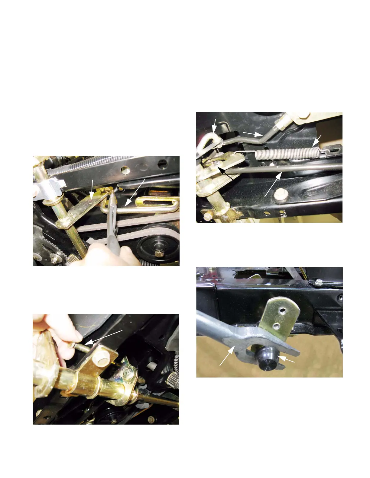
Figure 6.21
Clutch/brake shaft Rod
Figure 6.22
Travel limit pin
6. Unhook and remove the clutch/brake pedal
return spring.
7. Remove the cotter pin and flat washer that hold
the brake rod into the latch plate. Discard the
cotter pin.
8. Remove and discard the cotter pin that holds the
tensioner pulley control rod to the “cobra head”
arm on the drive control pedal. See Figure 6.23.
9. Remove and discard the push cap that holds the
drive control pedal shaft onto the clutch/brake
shaft. See Figure 6.24.
Figure 6.23
Return spring
Flat washer
Brake rod
Cobra head
Control rod
Figure 6.24
Tie-rod
separator
Push cap
 Loading...


