CVT Drive and brake system
66
10. Loosen the bolt that holds the left pedal shaft
support strap using a 1/2” wrench.
See Figure 6.25.
11. Remove the bolt that holds the right pedal shaft
support strap using a 1/2” wrench.
NOTE: This will allow the pedal shaft assembly
to hang-down slightly on the right side of the
tractor.
12. As the pedal shaft is lowered, and the drive con-
trol pedal shaft can be slipped to the right:
See Figure 6.26.
• The brake rod will slip out of the latch plate on
the brake pedal shaft.
• The rod that ties the arm at the left end of the
brake pedal shaft to the tensioner pulley bracket
will slip free.
13. Remove the bolt from the left side pedal shaft
support strap, and remove the pedal shaft
assembly from the tractor. See Figure 6.27.
14. Disconnect the cobra-head rod from the pedal
shaft tie plate. See Figure 6.28.
• Slip the tie plate off of the cobra head rod.
• Push the hex bushing out of the big end of the
pedal shaft tie plate.
• The hex bushing can be snapped-off of the
brake pedal shaft.
Figure 6.25
Left pedal shaft support strap
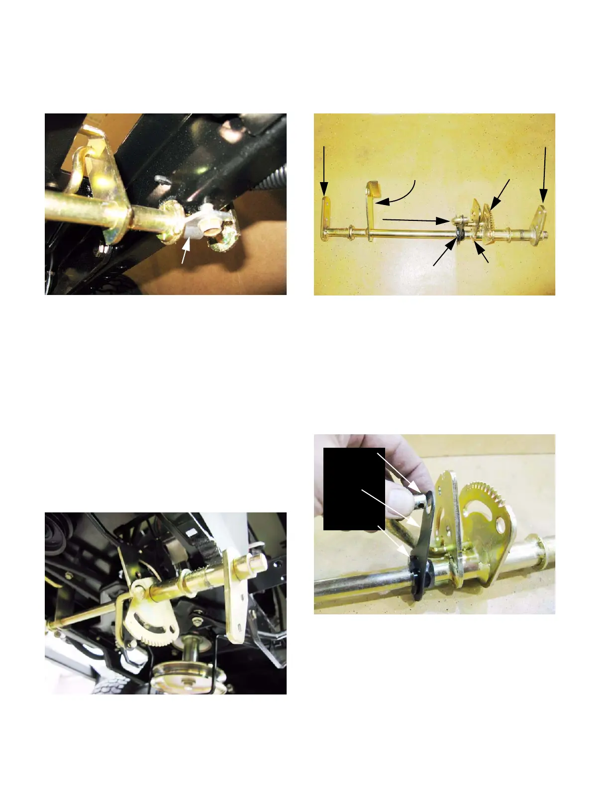
Figure 6.26
Figure 6.27
Brake pedal bracket Drive pedal bracket
Complete pedal shaft assembly
Arm for brake link
to tension pulley bracket cruise latch plate
Cobra-head
Tie plate Brake latch plate
Figure 6.28
Cobra-head
Tie plate
Hex bushing
 Loading...


