CVT Drive and brake system
82
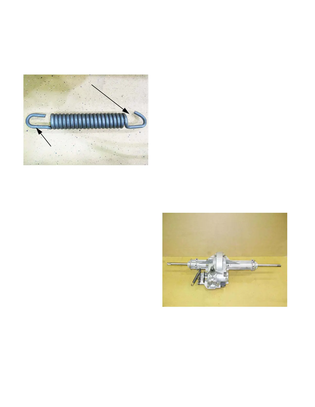
NOTE: The brake spring has a tighter hook on
the brake arm end than on the brake rod end. It
is much easier to disconnect the spring from the
rod. See Figure 6.84.
14. Carefully lift the transaxle onto a workbench for
disassembly as needed.
15. Installation notes:
15a. Check adjustment of the brake before
installing the transaxle.
15b. Connect both ends of the brake actuator
spring before lifting the transaxle back into
the tractor.
15c. Lube the Double-D axle shaft before
installing the wheels.
15d. The wheel spacer sleeves are of different
lengths: the short one goes on the right,
the long one goes on the left.
15e. Install the transaxle by reversing the steps
used to remove it.
15f. Tighten fasteners according to the torque
table at the end of this chapter.
16. Operate and test the drive system, brake sys-
tem, and all safety features before returning the
tractor to service
Transaxle repair
1. Assess the damage from the outside;
See Figure 6.85.
1a. If the tractor is within the warranty period,
is the damage consistent with a warrant-
able failure?
1b. If the tractor is beyond the warranty period,
is the transaxle feasible to repair?
1c. Are the axles bent?
1d. Is the housing broken from the outside-in?
1e. Is the housing broken from the inside-out?
1f. Spin-test:
• Will the input shaft turn in neutral?
• Will it drive the wheels forward in forward gear?
Hold the brake rotor and check input-shaft back-
lash. It should be .006”-.014” (.15-.36mm).
• Will it drive the wheels backward in reverse
gear?
Hold the brake rotor and check input-shaft back-
lash. It should be .006”-.014” (.15-.36mm).
1g. If it fails the spin test, are the brakes too
tight?
2. If further investigation is required to determine
the cause of the failure or to asses the feasibility
of repair, disassemble the transmission using
the following steps:
NOTE: steps #4 through #6 can be skipped if
this is a warranty-related autopsy.
Figure 6.84
Rod end
Arm end
Figure 6.85
 Loading...


