CVT Drive and brake system
72
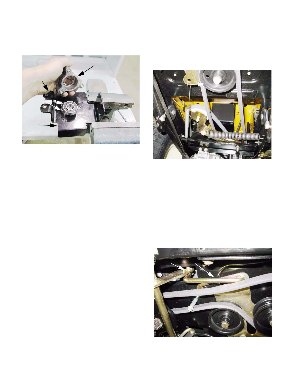
9e. Remove the three screws that fasten the
bearing holder to the bracket, and lift away
the bearing holder. See Figure 6.47.
9f. Inspect the bearings and variable speed
pulley.
• The bearings should turn smoothly, with no
unusual noise.
• The variable speed pulley should spin true in the
bearings.
• The center partition of the variable speed pulley
should slide up-and-down smoothly.
9g. Reassemble the variable speed pulley by
reversing the steps used to disassemble it.
10. Reinstall the variable speed pulley assembly in
the tractor by reversing the steps used to
remove it.
• Apply thread locking compound such as Loc-
Tite
TM
242 (blue) to the variable speed pulley
bolt. Tighten the bolt to a torque of 150-180 in-
lbs (17-20 N-m).
• Tighten the bearing holder screws to a torque of
90-135 in-lbs (10-15 N-m).
11. Run and test the drive system before returning
the tractor to service.
Belt control: tensioner pulleys
NOTE: The V-pulley can be removed from below
using a 1/2” wrench, with no disassembly
beyond removing the cutting deck.
See Figure 6.48.
NOTE: Confirm that the parking brake is
released before starting work.
1. Remove the mowing deck.
2. Remove the fenders, as described in the body
panels chapter of this manual.
3. Disconnect the rod that joins the arm at the left
side of the clutch/brake shaft to the drive belt
tensioner pulley bracket. See Figure 6.49.
• Remove and discard the cotter pin to disconnect
the rod.
Figure 6.47
Bearing cover
Bracket
keeper
Belt
Bearings
Figure 6.48
V-pulley
Figure 6.49
Cotter pin Rod