HYDRO. DRIVE AND BRAKE SYSTEM
40
13. Remove the left side pedal shaft support strap,
and lower the pedal shaft assembly out of the
tractor. See Figure 5.30.
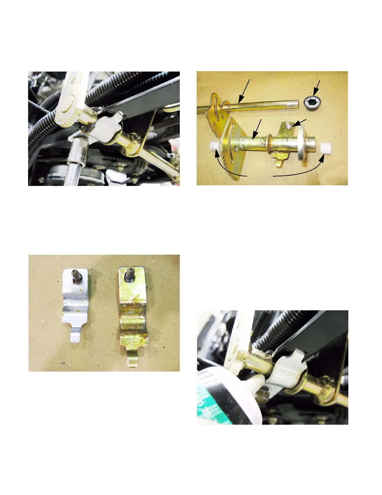
NOTE: The pedal shaft support straps are two
different sizes. The smaller strap holds-up the
left (brake pedal) end of the pedal shaft assem-
bly. The larger strap holds-up the right (drive
control pedal) end of the pedal shaft assembly.
See Figure 5.31.
14. Inspect the pedal shaft components individually.
Replace any parts that are worn or damaged.
See Figure 5.32.
• The plastic bushings that fit between the two
pedal shafts should be replaced any time they
are removed. Lubricate them with a dry PTFE or
graphite-based lubricant on assembly. NOT
grease.
• Replace the push cap and all removed cotter
pins with new parts.
15. Install the pedal shaft assembly by reversing the
steps used to remove it, then install the fenders.
15a. Lubricate the points where the pedal shafts
meet the frame with a good quality lithium-
based grease. See Figure 5.33.
Figure 5.30
Figure 5.31
Left side strap Right side strap
Figure 5.32
Clutch/brake pedal shaft Push cap
Drive pedal shaft Pedal shaft
support strap
Bushings
Figure 5.33
 Loading...


