Name Content
Current
measurement
AC 0 to 50A
(CT1, CT2)
(50/60Hz)
Voltage
measurement
AC 150 to 600V
(PT1, PT2)
(50/60Hz)
Compressor
Unit with 400V only :
26.0A
overcurrent Unit with 200V and 400V:
protection 15.0A
Phase sequence The phase sequence is detected
detection by sending the voltage
waveform to the controller.
4-13
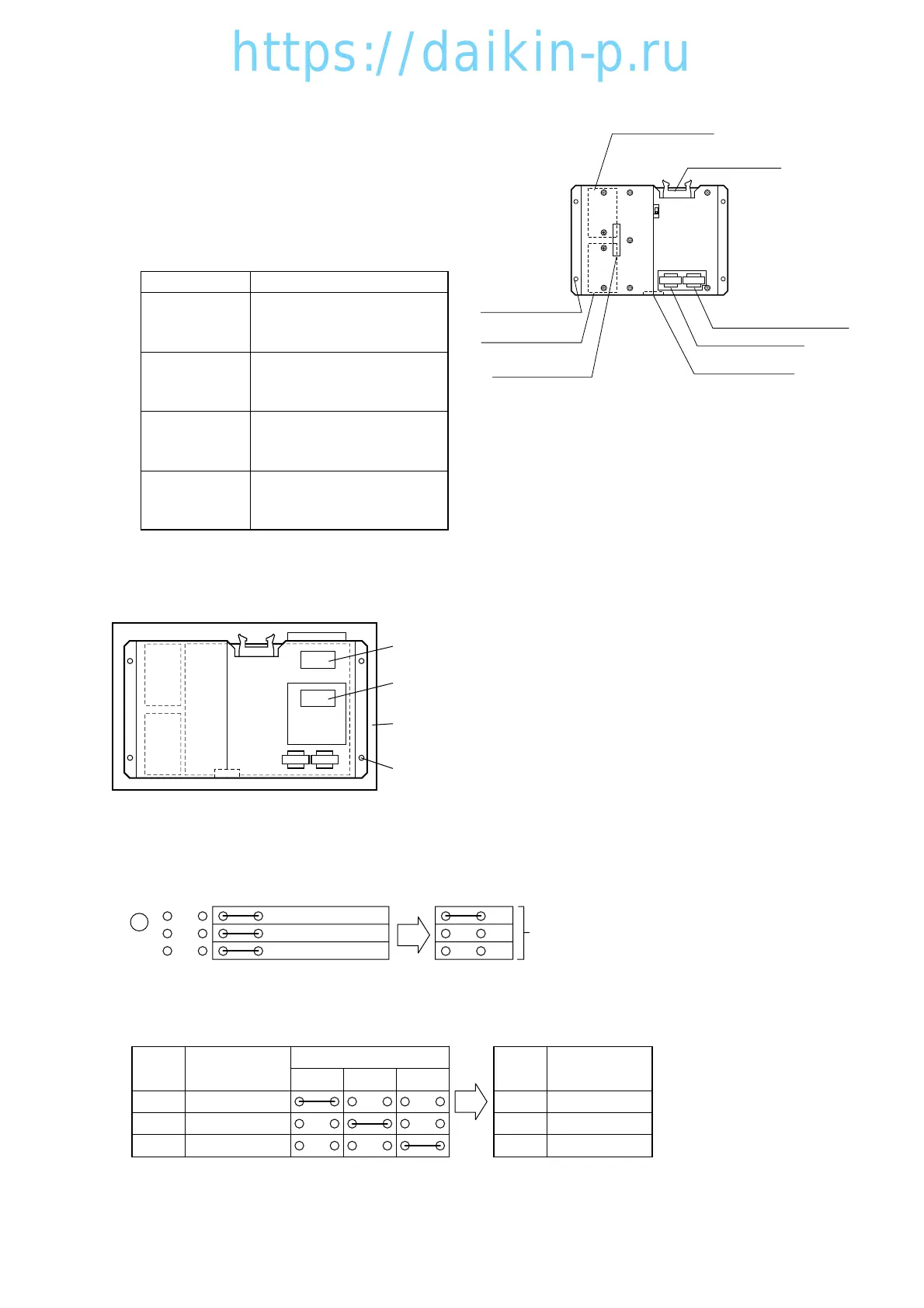
4.2.3 PT and CT board (EC9756)
Two function of the measuring device and
protector are integrated on this printed-circuit
board. This board works as an interface
between the main circuit (high voltage) and the
controller.
(1) Function
(2) Pre-assembly work
Before installing the PT/CT board (spare parts), cut jumpers and remove the mounting plate for the over
current setting.
(2-1) Overcurrent setting
Cut jumpers at section A according to the following chart in order to make the over current setting.
Example: over current setting for 10Hp single power
(2-2) Indication of check marks
After cutting jumpers, indicate check marks on the table B.
Example of check mark
indication
i Indication label of
applicable model
q CT1 (total current)
w CT2 (compressor current)
e PT2 (S-T voltage)
r PTI (R-S voltage)
t Connector (CN2)
for main circuit
y Connector (CN1)
for controller
u Mounting hole
(4 places)
Jumpers at section A
(back side)
Jumper check sheet at
section B
Mounting plate (Remove LXE10D. 10E)
Screws (4 pcs)
A
PT
PT
B
CN2
CN1
CT1 CT2
Table
J3 e Single 10
J2 w Dual 5
J1 q Dual 10
Spare parts In case of Single 10
Cut the J1, J2
jumper
J3
J2
J1
CASE Type
Jumper
J1 J2 J3
1 Dual 10
2 Dual 5
3 Single 10
CASE Check
1
2
3
✔
04LXE10E-A(9-24)07.2.1918:50ページ4-13
 Loading...