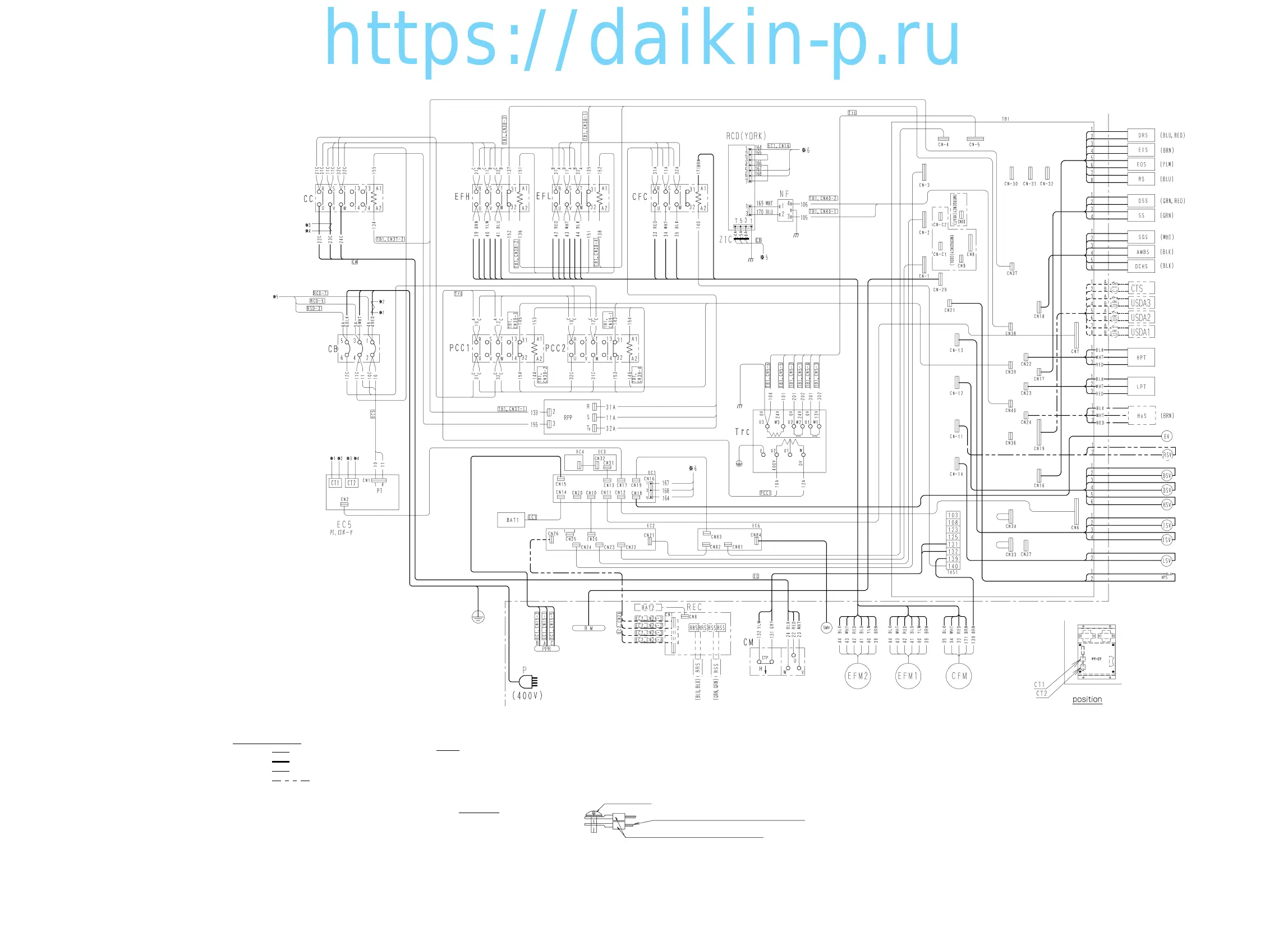
Notes for wiring
UL1015 AWG10 (5.5 mm ):
UL1015 AWG16 (1.25mm ):
-
C
-
line between terminals represents the jumper wire.
line represents the line in the box.
(1)
Note:
UL1015 AWG12 (3.5 mm ):
line represents the optional specification.
UL1015 AWG14 (2.0 mm ):
2
2
2
2
The terminal numbers and applicable cables in each
unit are as shown below.
(2)
-
A
-
-
B
-
line represents the external unit or junction cable.
BLK: Black, BLU: Blue, GRY: Grey
BRN: Brown, RED: Red, YLW: Yellow
WHT: White, GRN: Green
Line color
(3)
(6)
At the two tightening positions of round crimp terminals
with M3.5 insulating sleeve (FN type) or tightening
positions of round crimp terminal (FN type)
with M3.5 insulating sleeve and the round crimp terminals (FN type)
with M4 insulating sleeve,tighten with torques ranging from 11.2 to 13.8 kg.cm.
(from 1.1 to 1.3 N.m).
(7)
Prevent any contact of the wiring with the TrC coil.
(8)
The strong wiring must be separate from the weak wiring by 25 mm or more.
(9)
Wiring inside the machine should be laid in accordance
with GAH010-Z unless otherwise specified.
(10)
The colors in parentheses indicate distinction colors.
M3.5 screw
The larger size wire
must be placed under the smaller one.
M3.5 round crimp terminal (FN type)
(back-to-back)
(4)
Sequence chart of this diagram accords with the table.
(5)
When tightening the two round terminals, tighten as shown below.
When tightening the two terminals whose wire sizes are different,
the larger size wire must be placed under the smaller size one.
 Loading...