Design Guide | iC7 Series Liquid-cooled System Modules
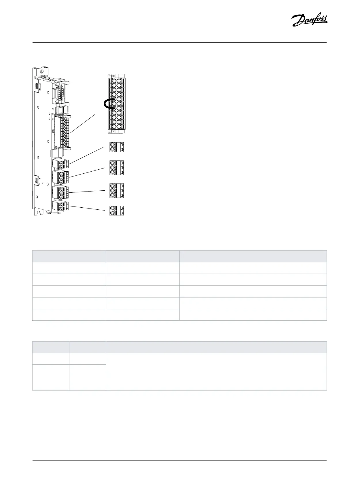
8.8 I/O and Relay Option Connections
11
13
15
17
19
21
23
31
33
35
37
12
14
16
18
20
22
24
32
34
36
38
X51
X101
X102
X103
71
72
1
2
3
4
5
6
7
8
Figure 103: I/O and Relay Option Terminal Block and Terminal Numbering
Table 28: I/O and Relay Option Signals
Terminal Function Connector type
X13 I/O terminal 2 x 11 spring force connector 0.2–1.5 mm
2
X51 Thermistor input 1 x 2 spring force connector 0.25–2.5 mm
2
X101 Relay 1 1 x 3 spring force connector 0.25–2.5 mm
2
X102 Relay 2 1 x 3 spring force connector 0.25–2.5 mm
2
X103 Relay 3 1 x 2 spring force connector 0.25–2.5 mm
2
Table 29: I/O Terminal Signals (X13)
Terminal Function Description
11 +24 V
out
12 +24 V
out
Control voltage output.
24 V DC (-15...+20%)
Maximum current 200 mA
Short-circuit protected
Danfoss Drives Oy © 2024.03 AJ475942178716en-000101 / 172K2848A | 101
 Loading...


