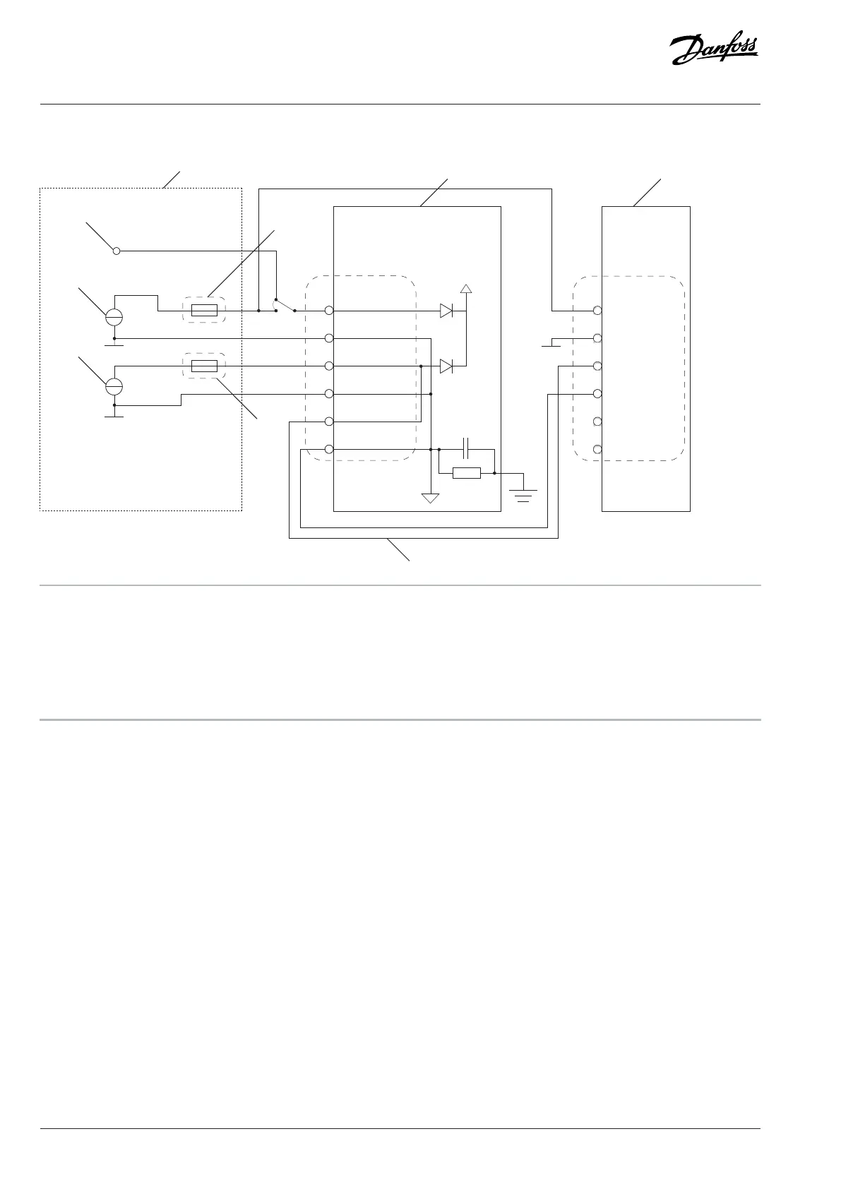
10.3.11 Wiring Diagrams of the +24 V Supply for the Control Unit
+24V input
GND
GND
GND
+24V output
62
63
61
+24V input
GND
GND
GND
+24V output
+24V ext input
A Internal +24 V supply (if provided) B Reference design, redundant +24 V power
C 3 A fuse D Control board
E Power daisy-chaining F Fuse (Fuse rating depends on the complete daisychained
system configuration. Maximum 10 A.)
G Primary external supply H External redundant supply
Figure 168: Wiring Diagram of Redundant Supplies
166 | Danfoss Drives Oy © 2024.03 AJ475942178716en-000101 / 172K2848A
Design Guide | iC7 Series Liquid-cooled System Modules
 Loading...


