Design Guide | iC7 Series Liquid-cooled System Modules
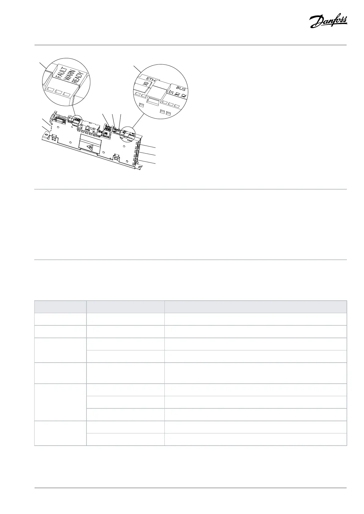
Figure 97: The Control Board
A Status indicators (FAULT, WARN, READY) B Fieldbus indicators (ST, X1, X2) and Ethernet port
indicators (X0)
1 Control panel connector (X9) 2 Fiber optic link to power unit (X80)
3 24 V DC supply (X62) 4 microSD card
5 RTC battery holder 6 Ethernet port (X0)
7 Ethernet port (X1) 8 Ethernet port (X2)
8.3 Definitions of the Indicator Lights on the Control Board
Table 21: Definitions of the Indicator Lights on the Control Board
Indicator name Function (color) Description
Fault On (red) Fault active
Warn On (yellow) Warning active
On (white) Ready for operationReady
Blinking 1 Hz (white) Power on, not ready
Fault+Warn+Ready Blinking (red + yellow + white) Winking from an external application. Can be used for identifying where the
external application is wirelessly connected to.
Off No link
On (green) Link OK, no data
X0 link activity
Blinking (green) Link OK, data communication
Off No link or 10 Mbps linkX0 link speed
On (orange) 100 Mbps link
For the description of the fieldbus indicators (ST, X1, X2), see the relevant application guide.
Danfoss Drives Oy © 2024.03 AJ475942178716en-000101 / 172K2848A | 95